

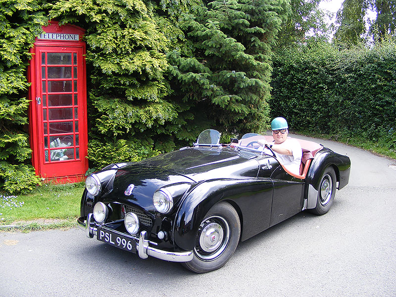
TR2
(1953-1955)


Lively performance, good looks and reasonably priced
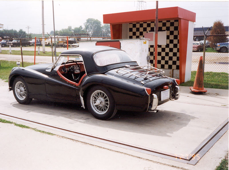
The TR2 was introduced in 1953 as Triumph’s bid to capture some of the budding sports car market in the U.S.A. A total of 8,636 TR2s were built between August 1953 and September 1955, a large fraction of which were exported to these shores. The TR2 is widely recognized as the car that “started it all” for Triumph in the U.S. The TR2’s combination of lively performance, good looks, and reasonable price made it a strong seller and led to the very successful TR line that we all know and love. Below you will find links to the general specifications and production history of the TR2, some pictures, and “Triumph TR2 Guide to Originality ” (originality tips compiled by Bill Lynn and Bill Redinger).
TR2 Survivors List
The Survivors List (at 3-31-2022) (Download)
Add your vehicle form (Download)
Scrapped vehicles list (at 3-31-2022) (Download)
A history of the TR2
compiled by Bill Redinger and John R. Davy
Changes by commission number
| Comm. No. | Description |
| 20SR | Earls Court Motor Show Car, October 1972 (20TS, or TR1) |
| TS-1 | First production 90hp TR2 |
| TS-1201 | Water filler moved from thermostat housing to radiator |
| TS-1301 | License plate lamp replaced red tail-stop lamp at center rear |
| TS-4002 | Long doors removed in favor of short doors and rocker panels |
| TS-4229 | Chrome front hinges added, inside bonnet release dropped in favor of Dzus fasteners, bonnet louvres reduced from four to two |
| TS-4500 | Side windows added to top for better rear vision |
| TS-5256 | Fixed window side curtains / zippers replaced wedge sliding type |
| TS-5443 | 10-inch front brakes instead of 9-inch |
| TS-6157 | Scuttle vent added |
| TS-8213 | Distributor altered |
| TS-8638 | Last production TR2, November 1955 |
General Specifications
Dimensions:
| Wheelbase | 88″ |
| Track (front) | 45″ |
| Track (rear) | 45 1/2″ |
| Ground clearance (under axle) | 6″ |
| Turning circle (between curbs) | 32′ 0″ |
| Tire size | 5.50″-15″ |
| Tire pressures | |
| Front | 22 lbs./sq. in. |
| Rear | 24 lbs./sq. in. |
| Length | 151″ |
| Width | 55 1/2″ |
| Height | |
| Top up | 50″ |
| Top of screen | 46″ |
| Top down, screen removed | 40″ |
| Weight, curb condition (excluding extra equipment), but complete with gasoline, oil, water and tools. |
2,107 lbs. |
| Axle weights | |
| Front | 989 lbs. |
| Rear | 896 lbs. |
| Shipping weight (dry) | 1,771 lbs |
Capacities:
| Fuel tank | 15 gallons |
| Engine sump | 13.2 pints |
| Gearbox | 1.8 pints |
| If fitted with overdrive | 4.2 pints |
| Rear axle | 1.8 pints |
| Cooling system | 16.8 pints |
| With heater | 17.4 pints |
Tappet Clearances: (Engine cold)
Intake valve 0.010″.
Exhaust valve 0.012″.
Contact breaker point gap 0.015″
Carburetors:
Twin S.U. H4
Jet needles – normal running FV
Front Wheel Geometry:
Camber static laden – 2 o
Castor – 0 o
King pin inclination – 7 o
Track – Toe-in 1/8″


Member Pages
If you would like your page added to this listing, please contact the webmaster.
Production Dates and Numbers
Commission Numbers and Selected Modifications
Sources: “Newton’s Illustrated Triumph Buyer’s Guide”, Moss Motor’s Triumph TR2-TR4A Spare Parts and Restoration Catalog, and Piggott’s” Original Triumph TR Restorer’s Guide”
Compiled by Carl Musson
TS 1 FIRST TR2
TS 213 Changed Handbrake Assembly
TS 550 (abt) Changed to Steel Bonnet & Spare Door
TS 869 Changed Choke Cable Assembly
TS 995 Wiper Spindles Separated to 14″
TS 1201 Changed Radiator, Thermostat & Housing
TS 1307 Changed Rear Lights, Modified Rear Wings
TS 1869 Changed Wheels to 4 1/2″
TS 2532 Change to 24″ muffler w/optional resonator
TS 2877 Changed Gear Lever & Shift Knob
TS 3268 Added Battery Box Drain Tube
TS 4002 Short Doors w/Rocker Panels (1955 Model Year Introduced)
TS 4229 Changed to Dzus Fasteners for Bonnet Release
TS 4307 Changed to 3-Window Hood (Top)
TS 5114 Changed Rear Hub Seals
TS 5255 Changed to Sliding Sidescreens, Factory fitted Hardtops
TS 5443 Changed Hand Brake Assembly, Larger Rear Brakes
TS 5980 Changed Overdrive Unit (Still Top Gear ONLY)
TS 6157 Added Dash Vent, Modified Bonnet Assembly
TS 6226 Changed Overdrive to Three-Speed Unit
TS 8636 LAST TR2

The TR2-TR3 Series Spotter’s Guide
by Ken Streeter, with input from Keith Martin and Bill Piggott
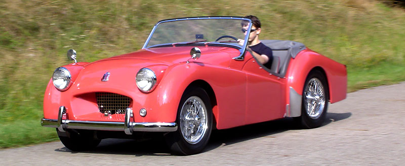
One model of TR2/3 can be difficult to tell from another unless you know what to look for. They all resemble bulldogs — short-squat, full of vigor, with distinguishing cut-away doors. The first was the TR2, built from 1952 to 1955. The early “small mouth, long door” has a small, recessed front grille and door skins that extend down to the bottom of the rocker panel.
To spot a really early TR2, check the wiper spindle spacing. The earliest cars had their windscreen wipers only 10.5 inches apart, which caused only a relatively narrow area of the windscreen to be wiped. At TS995, the spacing was increased to 14.5 inches. As the spindle holes are punched into the front scuttle and as it seems unlikely that anyone would ever alter this spacing during a rebuild, the narrow spacing remains a reliable guide to a genuine early TR2. This difference in wiper spacing is surprisingly noticeable on the cars and even in photographs, enabling one to look at a picture of a TR2 with an unknown identity and say with some certainty that it is a sub-TS995 car!
After the first few thousand TR2s, the Triumph factory responded to complains from owners who scraped the door bottoms on curbs by shortening the door skins, and introduced the TR2 model which has come to be known as the “small mouth short door.” Altogether, approximately 8600 TR2s were built.
In late 1955, the TR3 “small mouth” was introduced. This model can be recognized by its grill: the opening is still small, but the grill itself is no longer far recessed, but nearly flush with the front valence. Production reached nearly 17,000 for this model of TR3.
In 1958, Triumph opened up the grill to increase air flow and the TR3A “wide mouth” was born. At 58,236 cars, this is the most common of TR2/TR3 series.
The final version of the TR3 came in 1962. Triumph had released the svelte new TR4, but sales were initially disappointing, particularly in the USA. So the company put the 2.2 liter TR4 engine in left-over TR3 body stock, and created the TR3B, of which 3,331 were built. Without examining the engine compartment, it is difficult to tell a late TR3A apart from a TR3B.
There you go — you now know the quick and easy ways to differentiate between the models of the TR2/TR3 series.
TR2 Guide to Originality
By Bill Lynn, revised July, 2010, now includes more than 140 reference photos.
Technical Consultants: Bill Redinger and John Saunders. Photos: Bill Colaric, Blake Discher, Mike Duggan, Beverly Floyd, Jeffrey Kelley, Lou Metelko, Bill Redinger, Joe Richards, John Saunders, David Somerville, Justin Wagner, and Jim Williams.
References Include But Are Not Limited To: Triumph Factory Spare parts Catalogue (editions 1, 2, 3, & 4); Triumph factory repair manuals; 1954 & 1955 Triumph Factory Service Bulletins; Bill Piggott’s books Original Triumph and Triumph by Name Triumph by Nature; the personal research of Ian Gibson, Hans Kooij, Jeffery Kelley, The Roadster Factory, John Saunders, Justin Wagner, John Warfield, Pete Wigglesworth, and many others.
Edited and Adapted to HTML by Rick Reeves
Preface from the author:
What follows is an attempt to consolidate what we know about TR2 originality. I certainly don’t hold myself out as an expert or authority so your comments are welcome! It seems like we learn something new every day about TR2’s. In most cases, the information is taken from factory publications. In reality, the TS number when an engineering change was made may be slightly off. The engineers probably had a firm TS number in mind for the change, but the production floor often used up the old parts. Generally speaking the first 50 vehicles tended to be “hand made” and therefore vary somewhat from the later production cars. The information that follows focuses primarily on the post TS50 vehicles unless otherwise specified.
Exterior
The TR2 bodies were manufactured in the Triumph factory through circa TS1300. Thereafter the bodies were manufactured by Mulliners.
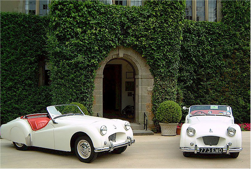
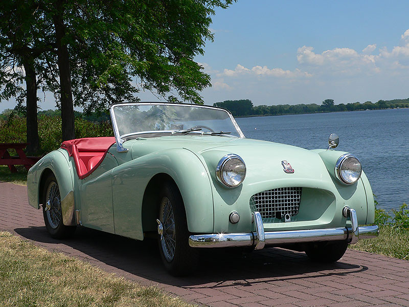
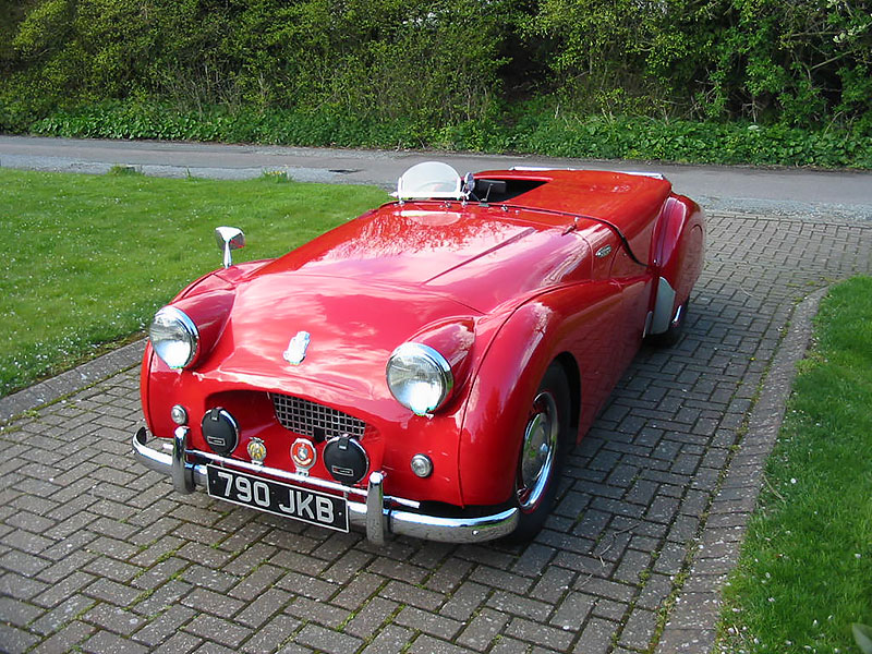
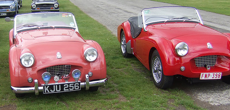
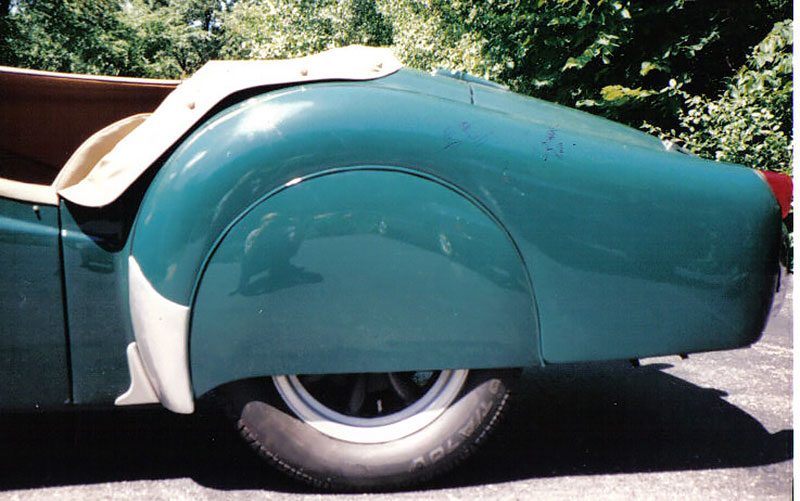
Body colors available included black, white (pearl white officially-although TS1, 2, &14 are known to be Ivory), geranium, olive yellow, and ice blue. Beginning with approximately TS1200, British racing green, and signal red were added as available colors. Click here for a picture showing a geranium TR2 next to a red TR2.
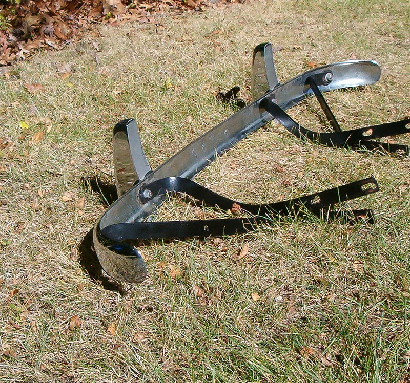
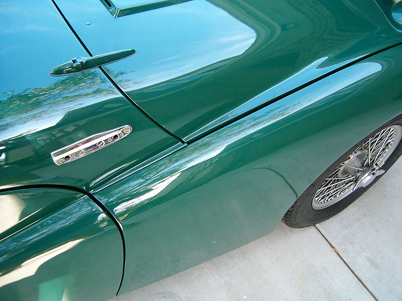
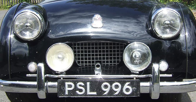
The bumper of the TR2 is unique to TR2’s and early TR3’s through commission number TS22013. The bumper brackets are made of four separate pieces of steel, are painted satin black, and bolt to the frame in four places (2 places on each side of the frame). The brackets are formed in such a way that they go around and beneath the front nose piece without bolting through the nosepiece itself. There are no support brackets for the upper ends of the overriders. The overriders are narrower than those used on TR3A’s and the curvature of the bumper was different (flatter). There were sometimes no holes drilled through the bumper for license plates forcing stateside dealers to provide a separate bolt-on bracket for the front license plate.
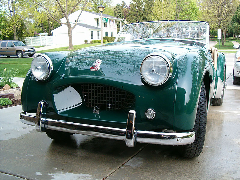
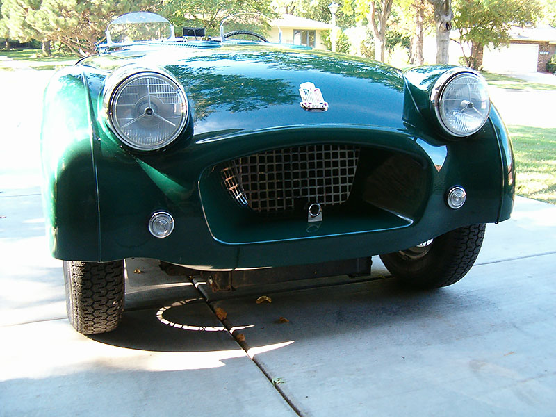
The nosepiece had a narrow “tunnel opening” in the grill area.
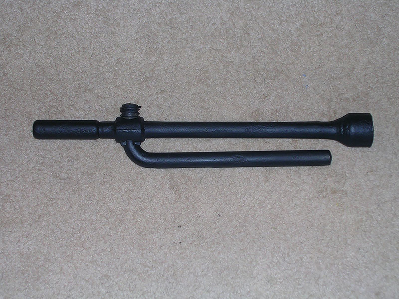
The hand crank guide (“bullnose”) located on the nosepiece tunnel in front of the grill was chrome plated.
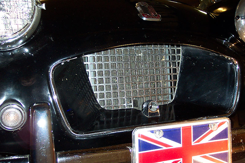
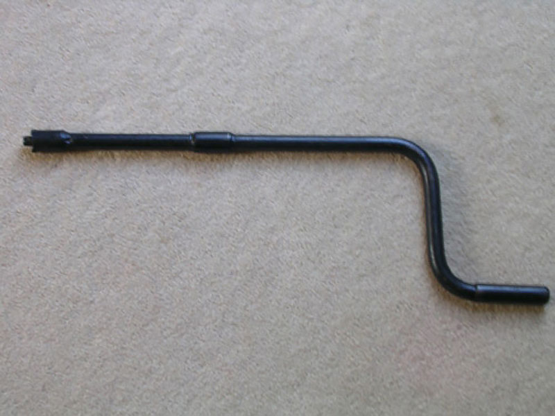
There was a square hole cut through the radiator to accommodate the hand crank.
The cast zinc/aluminum chrome plated grill was set back in the rear of the nosepiece tunnel opening. There were two types of grills. The most common type was the chrome plated cast zinc “pot metal” and on the very early TR2’s there was a chrome plated brass version.
Beginning perhaps as early as commission number TS5300 *, a one-piece, “U”-shaped, chrome (brass underneath the chrome) accent trim piece, known as “reveal molding”, was fitted around the outside of the opening of the grill tunnel. The trim piece covered the lower leading edge of the tunnel opening as well as the left and right sides but did not cover the top edge. This trim piece is different from the two-piece stainless steel accent trim used in the same place on TR3’s which covered the entire leading edge of the tunnel opening, top, bottom, and both sides. *(Note: It is known for sure that TS5317L was delivered from new with this “reveal molding”. If anyone has further information about when this reveal molding was first introduced, please let me know.)
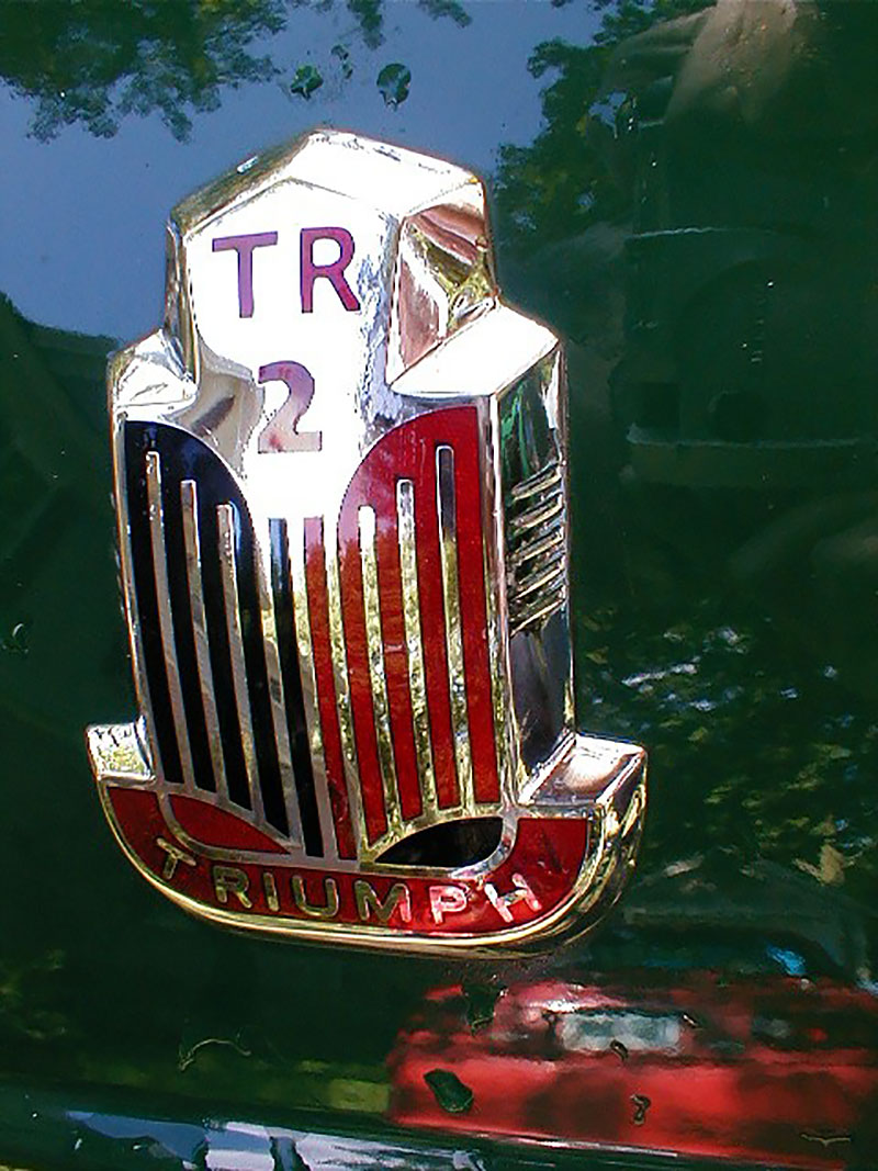
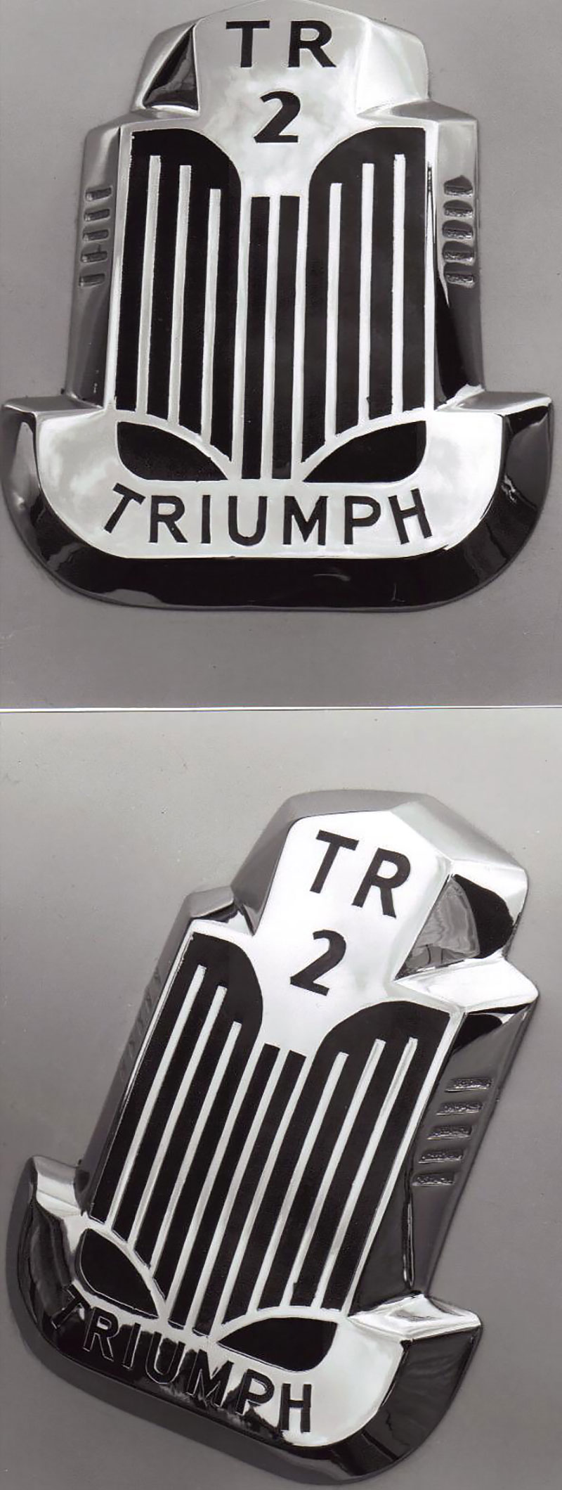
A red and black “open book” front badge was used on TR2’s and included the words “TR2” on the top and “Triumph” on the bottom. On TS1 through somewhere around TS30 – TS50, the actual front badge was the badge from the Standard 8 hand modified and changed to read “TR2”. This can be seen from the reverse side of the badge once it is removed. These early badges are easily distinguishable in pictures because unlike the later TR2 badges, the very early badges had the word “Triumph” in red enamel surrounded by chrome, whereas on the later TR2 badges, the word “Triumph” was in chrome surrounded by red enamel.
Body colored plastic wing beading was used on TR2’s instead of the stainless beading used on the TR3’s
The wing beading did not continue between the bonnet and front wings.
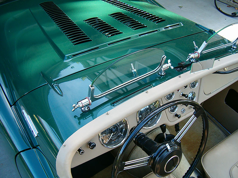
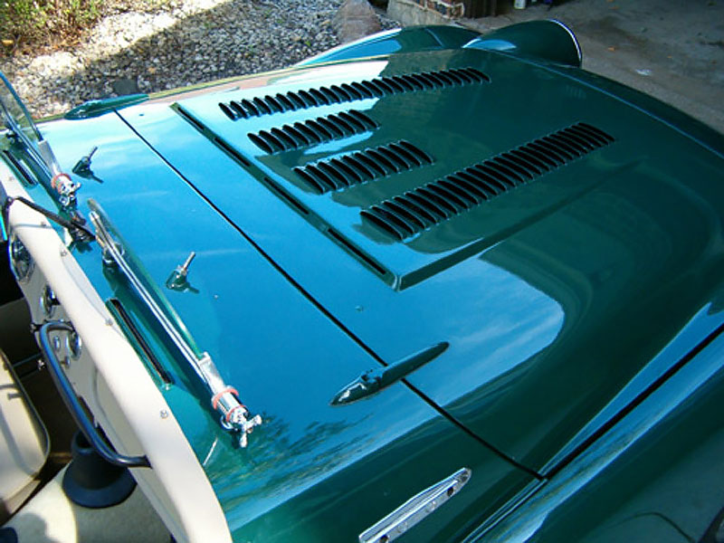
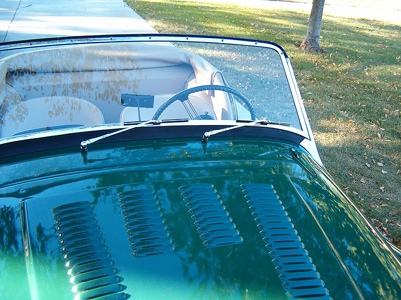
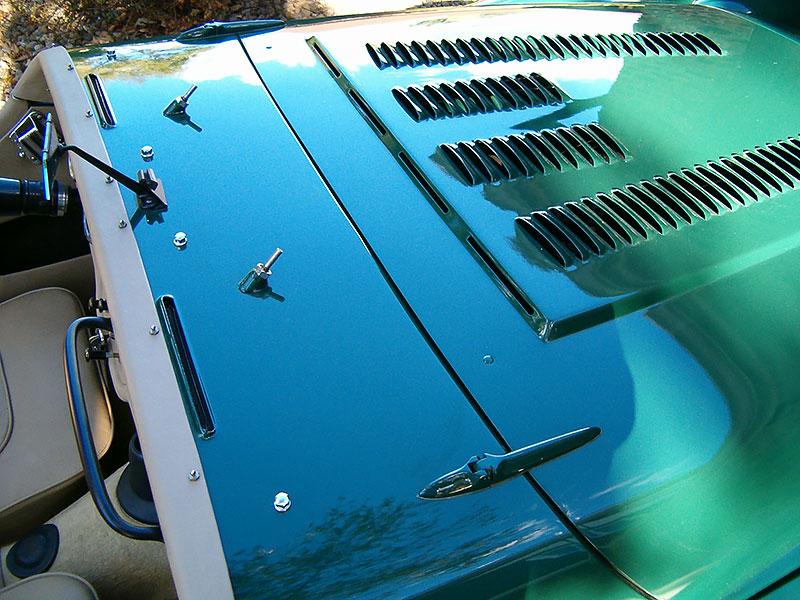
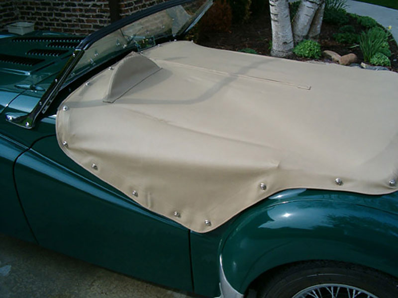
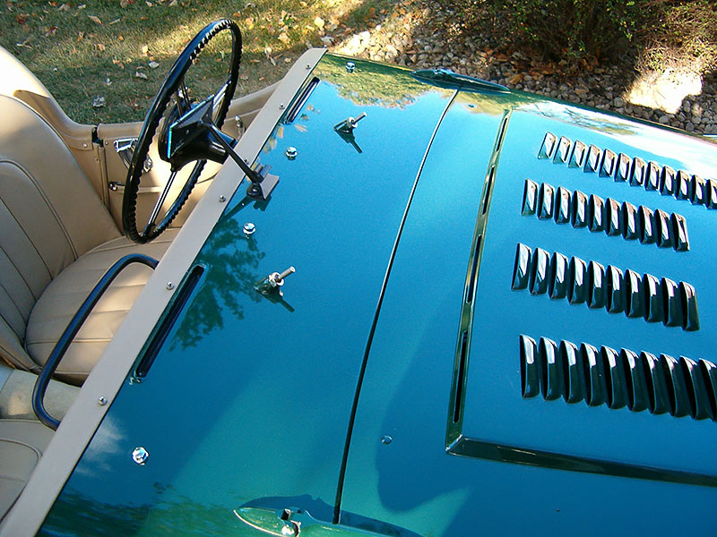
A cable release bonnet with four lateral louvers visible from the cockpit was used through commission number TS4228. (Note: multiple lateral louvers pictured are not original but were a popular period customization technique.) Dzus fasteners with a two louver bonnet were used on later TR2’s, beginning with commission number TS4229. There were two raised rivets exposed on the bonnet.
Approximately the first 500 TR2’s were fitted with an aluminum bonnet and an aluminum spare tire compartment cover. Aluminum bonnets on the early TR2’s had 4 raised rivets exposed on the bonnet
The TR2 model bonnet hinges were painted body color at least through commission number TS7228. There is some indication in the records that beginning with commission number TS7229, chrome bonnet hinges may have been fitted. However, there is little evidence that this scheduled change was actually implemented, at least on TR2’s destined for the “Home” market. Since numerous examples of painted bonnet hinges after commission number TS7229 can be found, the exact start date of the fitting of chrome bonnet hinges by the factory is debatable and remains unresolved at this writing. What is known with certainty is that chrome bonnet hinges were fitted to the TR3 model (beginning TS8637). Editions 1, 2, & 3 of the parts catalogues do not list chrome bonnet hinges. However, the 4th edition parts catalogue (dated July, 1962) indicates that chrome bonnet hinges were available through the dealerships, as an “alternative” to painted bonnet hinges, but with no starting commission number indicated. Bear in mind that the TR3, featuring chrome bonnet and boot lid hinges, had been introduced 5 years earlier than the printing of the 4th edition spare parts catalogue.
It is interesting to note that the Francorchamps, which were manufactured in Belgium from completely knocked down (CKD) TR2’s beginning in 1954, were fitted with both chrome bonnet and boot lid hinges. One wonders if it was Francorchamps that came up with the idea of chrome hinges. Is it possible Triumph adopted the idea of chrome hinges from Francorchamps?
The boot lid hinges were painted body color on all TR2’s. Chrome boot hinges were not introduced until commission number TS8637 (first TR3).
No cockpit air vent was present behind the bonnet until TS6157.
Windscreen wipers parked to the right (as you face the front of the vehicle) on the TR2 and TR3 models through commission number TS12567, instead of parking to the left as on later TR3 and TR3A models beginning with commission number TS12568. This difference is attributable to the placement of the windscreen wiper motor. The windscreen wiper motor was located on the left side on the TR2 and early TR3’s through commission number TS12567. Thereafter the windscreen wiper motor was relocated to the right side as you face the vehicle
Windscreen wiper wheelhouses (portion protruding through the bulkhead) were painted body color rather than chrome plated as on later models. The large retaining nut was chrome plated however.
The windscreen wiper wheel houses were approximately 10¼ inches apart on commission numbers TS1 through approximately TS994. Thereafter the wheel houses were approximately 14½ inches apart.
The rubber seal on top of the windscreen on perhaps the first 1000 or less TR2’s was narrow and did not wrap around the rear edge of the windscreen. Later TR2’s incorporated the more common top windscreen seal which wraps around the rear edge of the windscreen. This seal was then continued through the TR3A/B models.
Full length “long” doors were present through commission number TS4001, i.e., no outer rocker panels were present under the doors. Beginning with commission number TS4002, TR2’s had outer rocker panels under the doors and therefore had (short doors)
A special door seal was used on the inside bottom edge of the “long door” models. The seal was “J” shaped with the short leg of the “J” pointing upwards at the front of the door, with the long part of the “J” then running backwards from there on the bottom edge of the entire length of the door. The seal was glued to the door, was made of rubber, and formed an air seal between the door and the inner rocker panel when the door was closed.
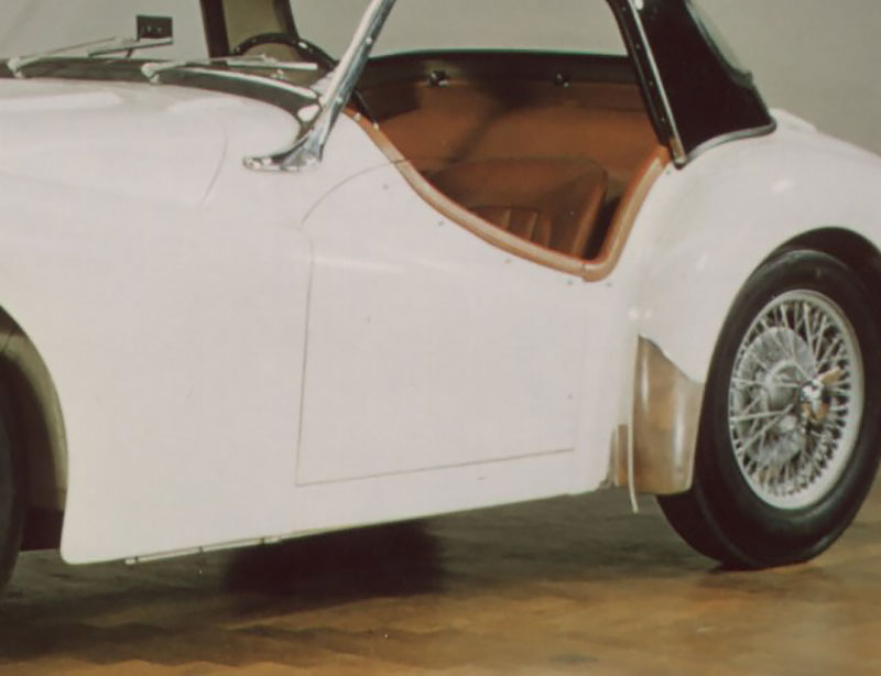
No exterior door handles were present on TR2’s.
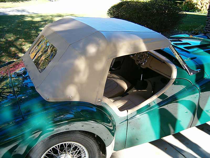
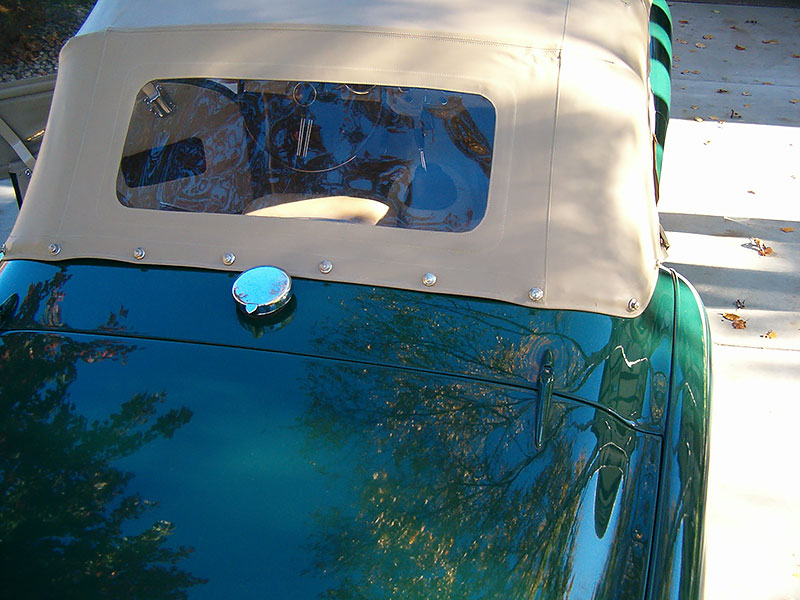
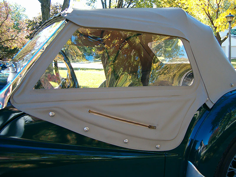
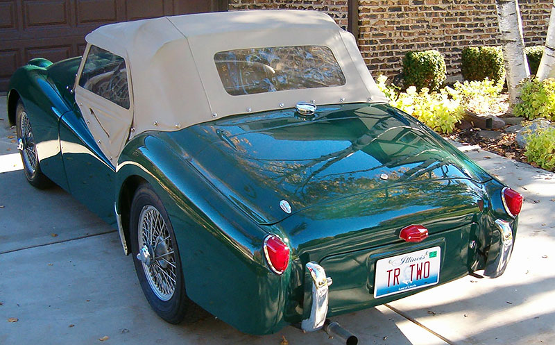
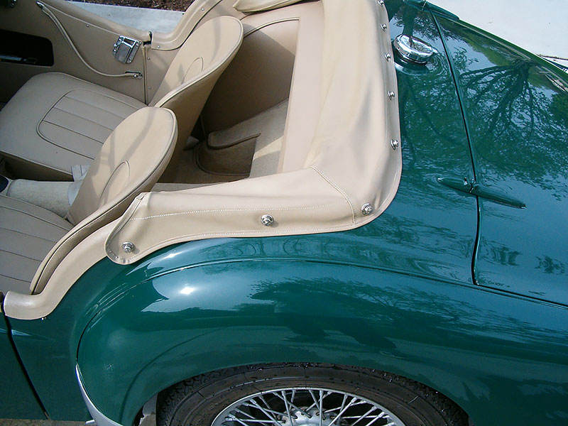
The hood (convertible top) had a single rear window and was made of three separate pieces of vinyl sewn together – not heat welded – through commission number TS4306. Beginning with TS4307, hoods (tops) had three rear windows for better visibility. Convertible top colors available included initially ice blue, geranium, blackberry, and later, black, white, and fawn.
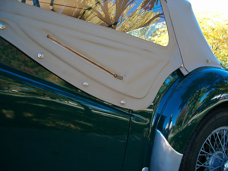
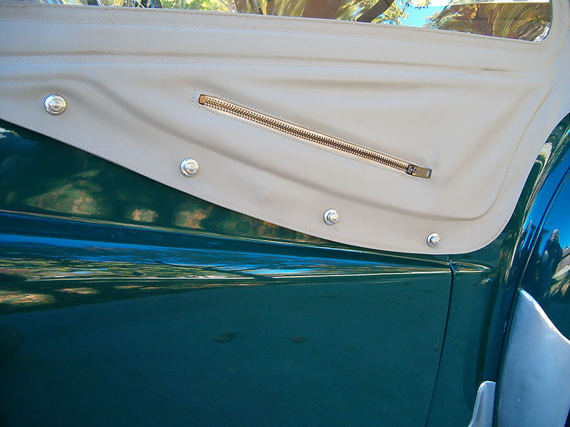
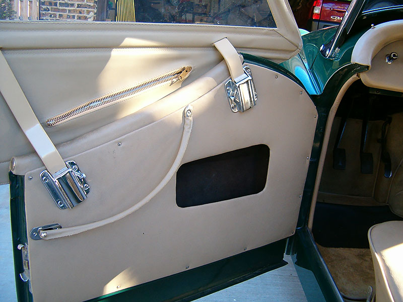
The TR2 sidecurtains had sewn-in single piece windows through TS8636. As indicated elsewhere, the sidecurtains were attached to the doors with baby Tenax fasteners through TS5255. Beginning with TS5256, sidecurtains were attached with Lift-The-Dot fasteners. The two piece sliding window sidecurtains were fitted from the factory for hardtop models.
Sidecurtains had a two-sided pull tab zipper sewn into the bottom flap for access to the interior door pull since no exterior door handles were present. This zipper was present through TS8636. TR2’s that were equipped from the factory with hardtops, were fitted with sliding window type sidecurtains with no zipper; however, the flexible lower flap was still present on the sidecurtains.
There were only three Tenax fasteners on the doors for attaching both the side curtains and tonneau cover for approximately the first 100 TR2’s. Thereafter, there were four fasteners on the doors for attaching the side curtains and tonneau cover (Note: larger Tenax fasteners are pictured).
Sidecurtains were secured to the exterior of the door with baby Tenax fasteners through at least commission number TS3513 (Note: larger Tenax fasteners are pictured). There is some evidence that beginning with TS3514, the larger Tenax fasteners may have been fitted. However, this has been difficult to verify with my own research. Beginning with commission number TS5256, Lift-The-Dot fasteners were used . There is some evidence there may have been a mixture of Tenax and/or Lift-The-Dot fasteners used in combination during the transition period. The area below the sidecurtain window could be flipped up if the fasteners were loosened to access the interior door pull.
The hood (convertible top), hood sticks cover, and tonneau cover were also attached with baby Tenax fasteners through TS3513 (Note: larger Tenax fasteners are pictured). Beginning with commission number TS3514 the larger Tenax fasteners were used up through commission number TS5255. Thereafter Lift-The-Dot fasteners were used.
The boot lid had no handle. Instead, there was a keyed lock in the center where the handle was located on later cars. This feature continued on early TR3’s through commission number TS22013.
Two budget locks, located parallel to the keyed lock on the left and right corners, were used to secure the boot lid. Corner budget locks were actuated using the same “T-handle” used to open the spare tire compartment.
The budget locks on the boot lid were identical to those used for the spare tire compartment cover but were covered with chrome “fig leaf” covers instead of the “toilet seat” covers used on the spare tire compartment cover.
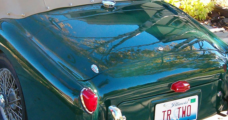
There were no separate turn signal lights present on the rear apron of the TR2’s. Outside tail lights were wired as turn signals and running lights. The outside tail lights were not wired as stop lights.
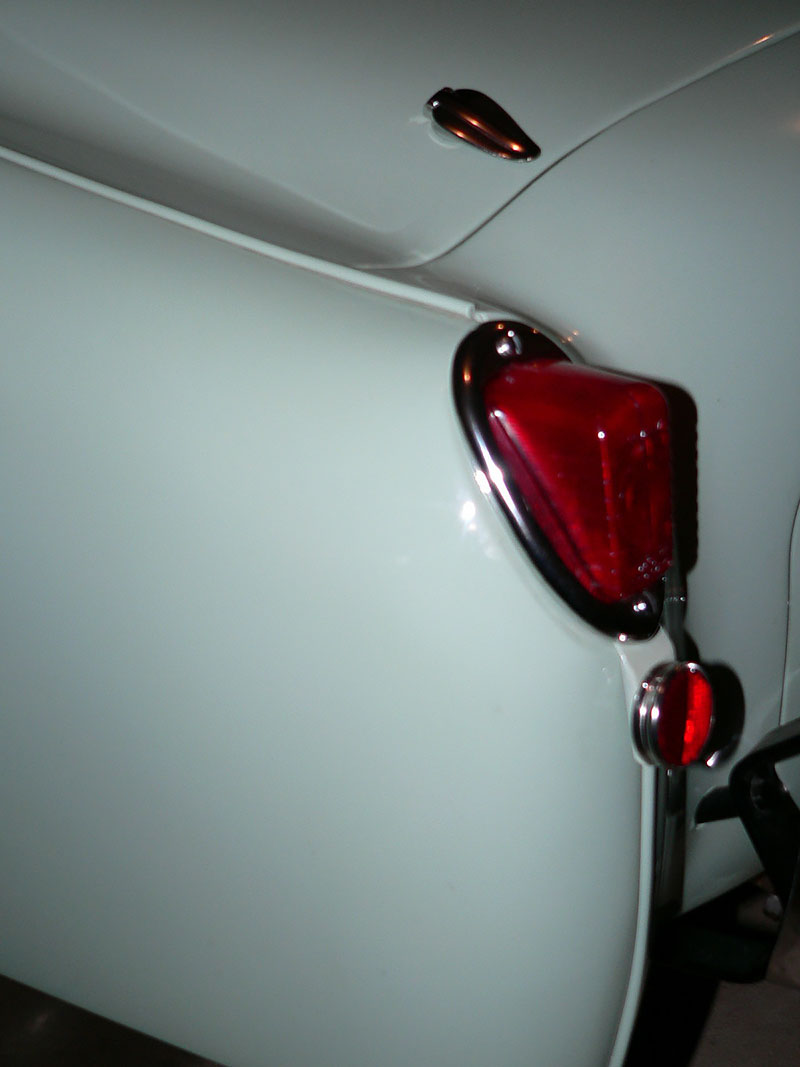
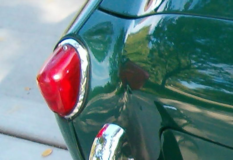
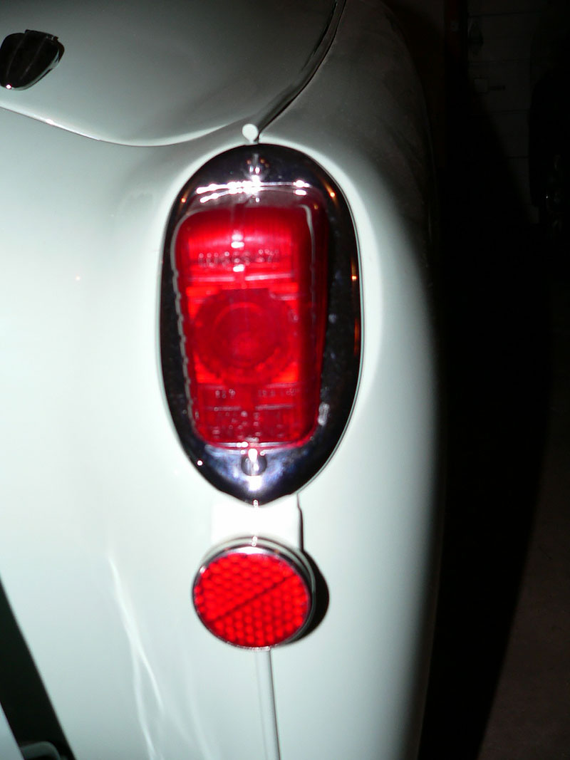
Early outside tail lights were rectangular similar to those used on MG-TDs, but the matching chrome bezels were completely different and not interchangeable with the MG-TDs. Early rectangular tail lights were used on commission number TS1 through approximately TS1306. The rectangular tail light lenses on TS1 are known to be made of glass but TS2, TS3, & TS14 were fitted with rectangular plastic lenses suggesting that virtually all of the TR2’s were fitted from the factory with the less expensive plastic tail light lenses. (Please advise if you have evidence to the contrary.) Beginning with approximately TS1307 and continuing through the TR3B’s, the more common oval tail lights were used.
A round reflector was “hung” just below each tail light on TR2’s for the “Home” market (UK and perhaps Europe) for commission numbers TS1 through approximately TS1306. This was a legal requirement in England and Europe. The reflector was not required in the USA market although some examples can be seen in the USA. The reflector was necessary with the rectangular tail lights because they did not include a reflector inside the plastic lens. A reflector was present in the later oval type tail light lens starting with approximately TS1307.
The brake light on TR2’s was located above the rear license plate only. The brake light was a combination brake and license plate light with a plastic red lens. This same center brake light was used on TR3’s through commission number TS22013.
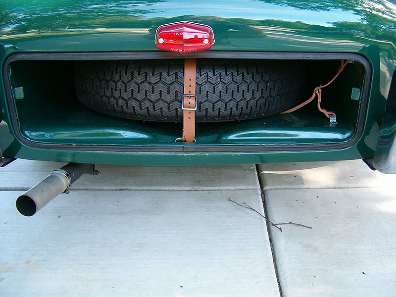
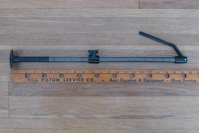
The lifting jack was stowed in the spare tire compartment. Early jacks (provided for commission numbers TS1 through TS5468, according to the factory service bulletin) were made of a piece of all thread rod material with an articulated handle and a round base plate. Beginning with commission number TS5469, the later style, stronger jack was provided coincident with the “beefing up” of the frame lifting point.
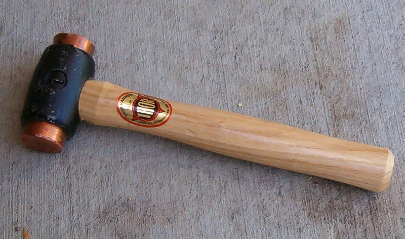
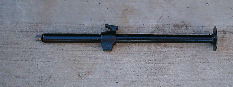
A wheel brace (lug wrench) was provided if the vehicle was fitted with steel wheels. The first 1000 or so TR2’s used smaller 11/16 in. lug nuts like those used on the Mayflower so the lug wrench was necessarily somewhat smaller. Thereafter the larger 7/8 in. lug nuts were used and the provided lug wrench was changed to match the larger lug nuts. A knock-off hammer was provided if wire wheels were fitted. Both the lug wrench and knock-off hammer (if wire wheels were fitted) were stowed in the spare tire compartment.
Under Bonnet
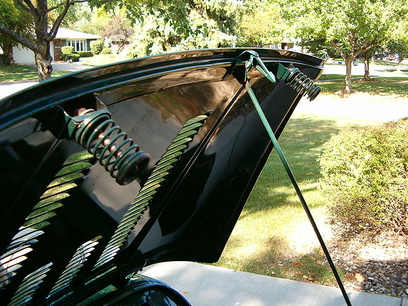
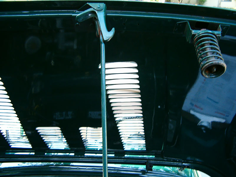
Bonnet springs and guide pins were present on the front left and right of the underside of the bonnet through commission number TS4228.
The bonnet prop rod and safety catch lever through commission number TS4228 were different. The safety catch lever pointed to the right as you faced the vehicle.
The bonnet prop rod receiving end bolted to the front top of the nosepiece and did not include a spring through commission number TS4228.
The bonnet latching mechanism for cable release bonnets was present on the inner wheel arches on the left and right sides through commission number TS4228.
The bonnet release cable was present on the inner left wheel arch (as you face the vehicle) inside the engine compartment. The cable looked like a choke cable, protruded through the bulkhead, and attached to the wheel arch with a single metal clip, approximately 1/4 inch wide. A second cable ran between the bonnet latches from right to left.
Beginning with commission number TS4229 and continuing through the TR3B model, the complicated bonnet cable release mechanism was replaced with two chrome plated Dzus fasteners located on the right and left sides of the front portion of the bonnet. The Dzus fastener bonnet locks were actuated manually by using the same coach key provided for the boot and spare tire compartment budget locks. In addition, a new, center bonnet lift spring was introduced which included a slot for the receiving end of the prop rod and safety catch. This bonnet lift spring mechanism was attached to the front nosepiece.
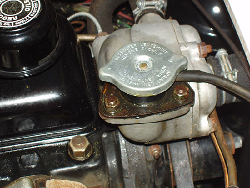
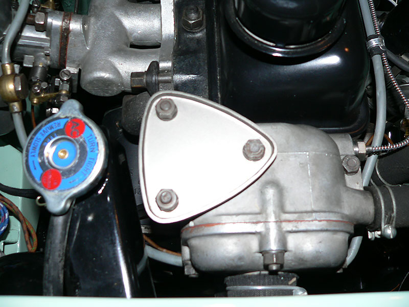
The first and likely second TR2’s had no neck extension on the radiator. Beginning with approximately TS3, the radiator had the standard radiator neck extension with radiator cap for filling purposes as was used on all Triumphs through TR4’s. On the early radiators (TS1 through approximately TS1200) the fitting for the top radiator hose was approximately 1¼ inches from the neck extension whereas on the later radiators the distance was approximately 2¼ inches from the neck extension. This difference is attributable to the different thermostat housing used on the early TR2’s (TS1 through approximately TS1200).
As indicated above, a special thermostat housing located on the engine block was used on commission number TS1 through approximately TS1200. On TS1 and likely TS2, the radiator cap was located on the special thermostat housing. Beginning with approximately TS3 through TS1200, a triangular blanking plate was fitted to the top of the special thermostat housing since the radiator filler cap was now located on the radiator neck extension. Beginning with TS1201 and continuing throughout the TR4 model, the more familiar standard thermostat housing was used.
All TR2 radiators originally had a tin plate, generally soldered to the top of the radiator, which included the manufacturing date of the radiator. This tin manufacturing plate often rusted away or otherwise disappeared if the radiator was ever removed and “boiled out”.
Beginning with TS3512, a bolt-on steel frame crosspiece was added to the frame underneath where the radiator bolts to the frame. The purpose of this crosspiece was to protect the lower radiator tank from parking curb damage.
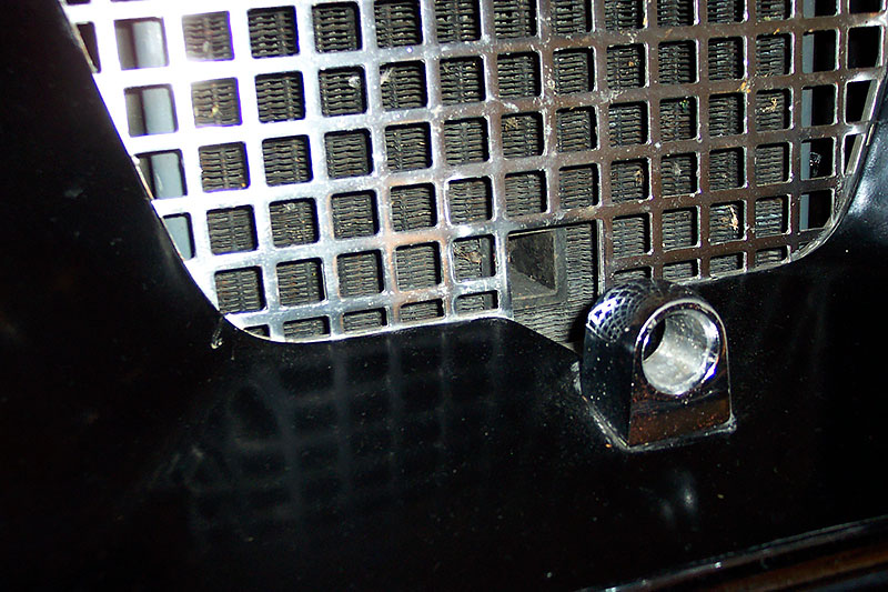
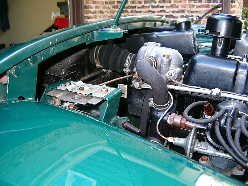
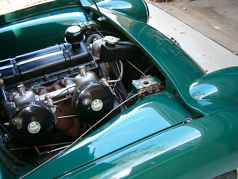
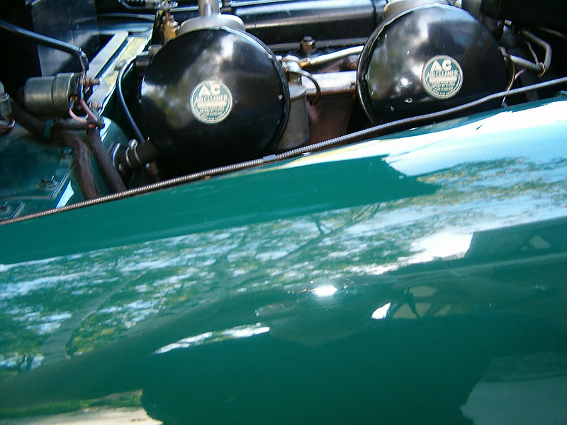
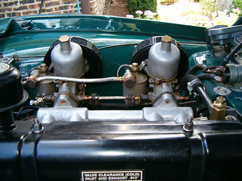
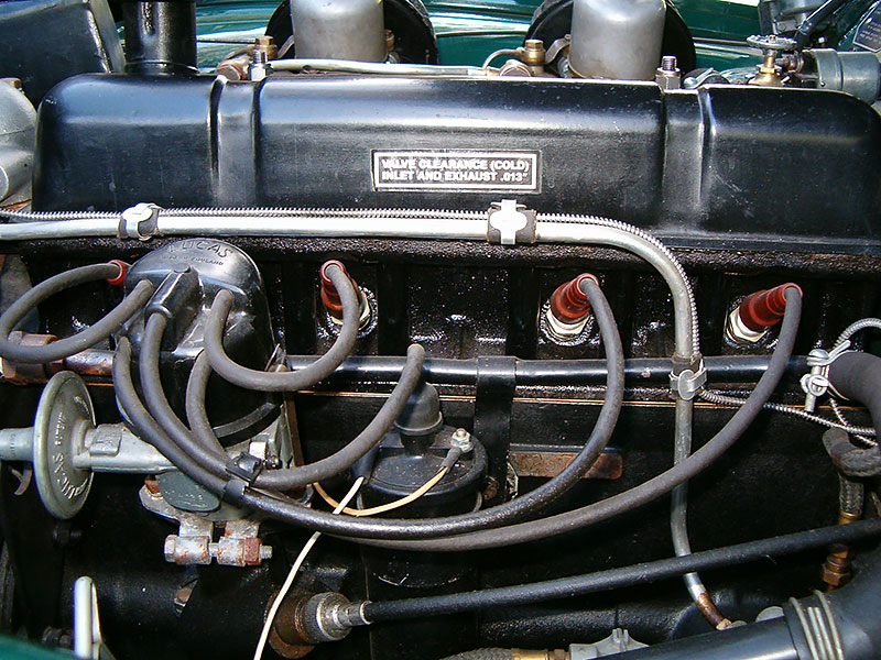
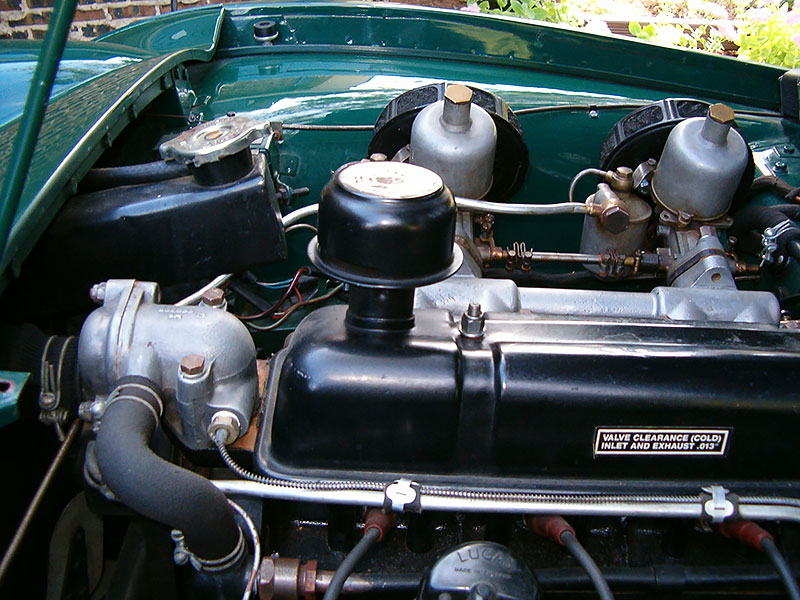
The engine block was painted satin black.The engine number is stamped into the right side of the engine block just to the right of the ignition coil. The engine number begins with the letters TS and ends with the letter E unless the engine was replaced by the factory or authorized dealer in which case the engine number may end with the letters FR. The factory reconditioned (FR) engines in England were often painted a different color (blue) and a tin plate with the date, rod bearing specifications, etc. was riveted over the original engine number plynth. The TS number on the engine block should normally be higher than the vehicle commission number by no more than 100 in the early TR2 model run and no more than 400 by the end of the model run. For examples, TS1LO was fitted with engine number TS3E, whereas TS8637 (first TR3) was fitted with engine number TS8997E. A few examples can be found where the engine number is lower than the commission number. This was more likely to occur in the first 1000 or so commission numbers. The engine numbers were not used by the factory on Triumphs in strict sequential order. Some engines within the sequence were sold and used in other vehicles, e.g., the Swallow Doretti’s, Francorchamps & Morgans. The oil filter canister was painted black, silver, or (AC-Delco) sea green. 1½ inch SU H4 carburetors were standard on all TR2’s and were bolted to the intake manifold with two bolts rather than four bolts. Beginning with the TR3, the larger (1¾ inch) SU H6 carburetors were used which were bolted to a revised intake manifold with four bolts. The air filters were black or silver and appear to be the same as those used on the TR3A but had a smaller opening on the rear to match the smaller, two bolt H4 SU carburetors. The bolt pattern on the rear of the air filters caused the filters to be centered on the carburetors rather than offset forward like on the later TR3A models which used the larger, four bolt H6 SU carburetors. A round sticker was present on each TR2 air filter. The large letters “AC” were printed on the sticker in white on a blue background along with some additional wording. The intake manifold was unique to TR2’s and early TR3’s to accommodate the smaller 1½” H4 SU carburetors and the different (“low port,”) cylinder head. The cylinder head was also unique to the TR2’s and early TR3’s and was used through engine number TS9350E. The cylinder head became known as the “low port” type as opposed to the “high port” types used on later Triumph models. The “low port” cylinder head is easily recognizable side-by-side next to a “high port” cylinder head. The round intake openings are much lower on the “low port” cylinder head than those on the “high port” cylinder head. With the cylinder head bolted to the engine the difference is more difficult to see. The “low port” cylinder head is flat across the top where the intake manifold bolts to the cylinder head whereas on the “high port” cylinder head, where the intake manifold bolts to the cylinder head, there is a pronounced arch above each of the four cylinders where the intake ports would be located.The TR2 valve cover was painted satin black rather than chrome plated.
The painted TR2 valve covers had a decal on the right side of the valve cover (as you face the vehicle) which gave the “cold” valve clearances in white letters.
The TR2 used a taller oil breather cap with a unique decal. The oil breather cap was painted satin black. If you are having difficulty locating a correct oil breather cap, it is my understanding that the same oil breather cap was used on the contemporary Rover P4 & P5 models.
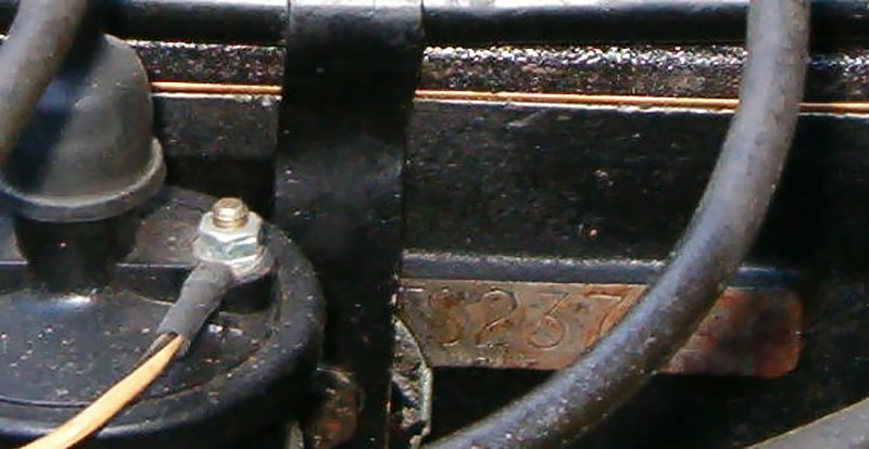
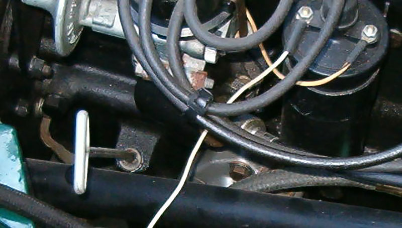
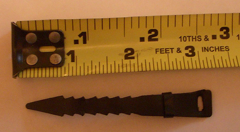
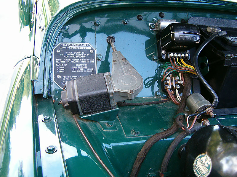
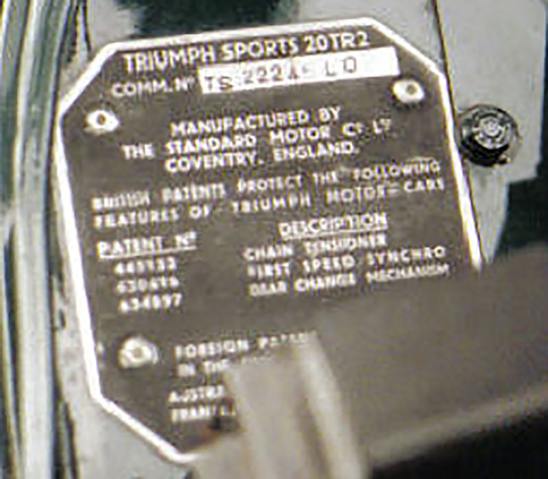
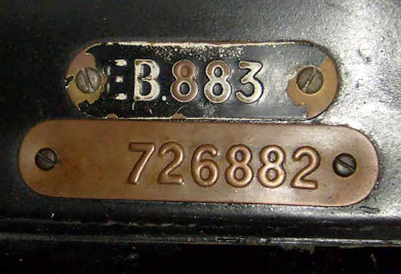
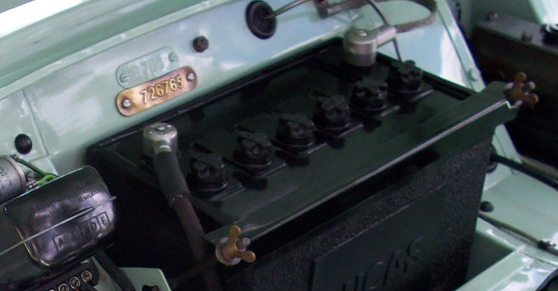
Only a front camshaft bearing was used on early TR2 engines until engine number TS8997E. Thus, the retaining bolts for the camshaft bearings were not present on the right side of the engine (as you face the vehicle) until engine number TS8997E. A unique distributor was used on the TR2. It is identifiable only by the part number DM2 40403 embossed on the side of the distributor pedestal and was used on engine numbers TS1E through TS8212E. Thereafter distributor part number DM2 40480 was used through approximately 1960. There was a plastic retaining strap holding the coil wire and the third & fourth spark plug wires together just to the right of the distributor cap. The plastic retaining strap dimensions were approximately 3 1/4 inches in length. The restraining strap is approximately 7/16 inches wide at the clasp end, and approximately 3/8 inches wide throughout its main length (arrowhead notches). The windscreen wiper motor was mounted on the left side (as you face the vehicle) on TR2 and early TR3 models (commission numbers TS1 through TS12567). As previously indicated, the windscreen wipers pointed to the right when in the “at rest” position. The commission number plate (vehicle identification number) is unique to the TR2 and is riveted to the bulkhead just behind the windscreen motor on the left side of the vehicle (as you face it.)Just above the battery are two body number tags screwed (not riveted) to the bulkhead. The first tag will start with the letters “EB” followed by 4-6 digits and was used for fully trimmed bodies all the way through the TR3A’s. The “EB” number is generally close to the original commission number but slightly higher. This was the body number designation used by the factory when the bodies were fully trimmed out with interiors. The second, lower body number tag, which consists of all digits, is the official body number used by Triumph. This six or seven digit body number is what appears in the official Triumph factory vehicle build records for all TR2’s and TR3A’s
Beginning with the TR3B’s, the two separate body number tags were no longer used. Instead, the bodies were manufactured by Foreword Radiator and had a single body number tag which carried the designation TSF followed by 1 to 4 digits (TSF 1 through TSF 3350).
It is debatable whether or not the body number tags should appear in their natural brass color or if they were painted the original body color. My personal opinion is that the EB body tag was painted body color and the lower all digit body number tag was unpainted natural brass. However, seemingly “original” vehicles are found with either natural brass body number tags or body number tags painted the original body color.
The battery cable terminal ends were the Lucas “helmet” type and attached to the battery with a single metal screw through the top of the lead “helmet. The word “Lucas” was cast into the battery cable terminal ends.
The positive ground battery cable was un-insulated, braided, steel wire. The negative battery cable was insulated with a braided solid black cloth exterior.
The battery hold- down bar was painted semi-gloss black and was attached with tall shoulder wing nuts.
Beginning with TS3288, a battery box drain was added. Prior to TS3288, no drain tube was present.
The wiring harness was covered on the exterior with a solid colored black braided cloth.
A Lockheed combination brake and clutch master cylinder was used on the TR2 and TR3 through commission number TS13045.
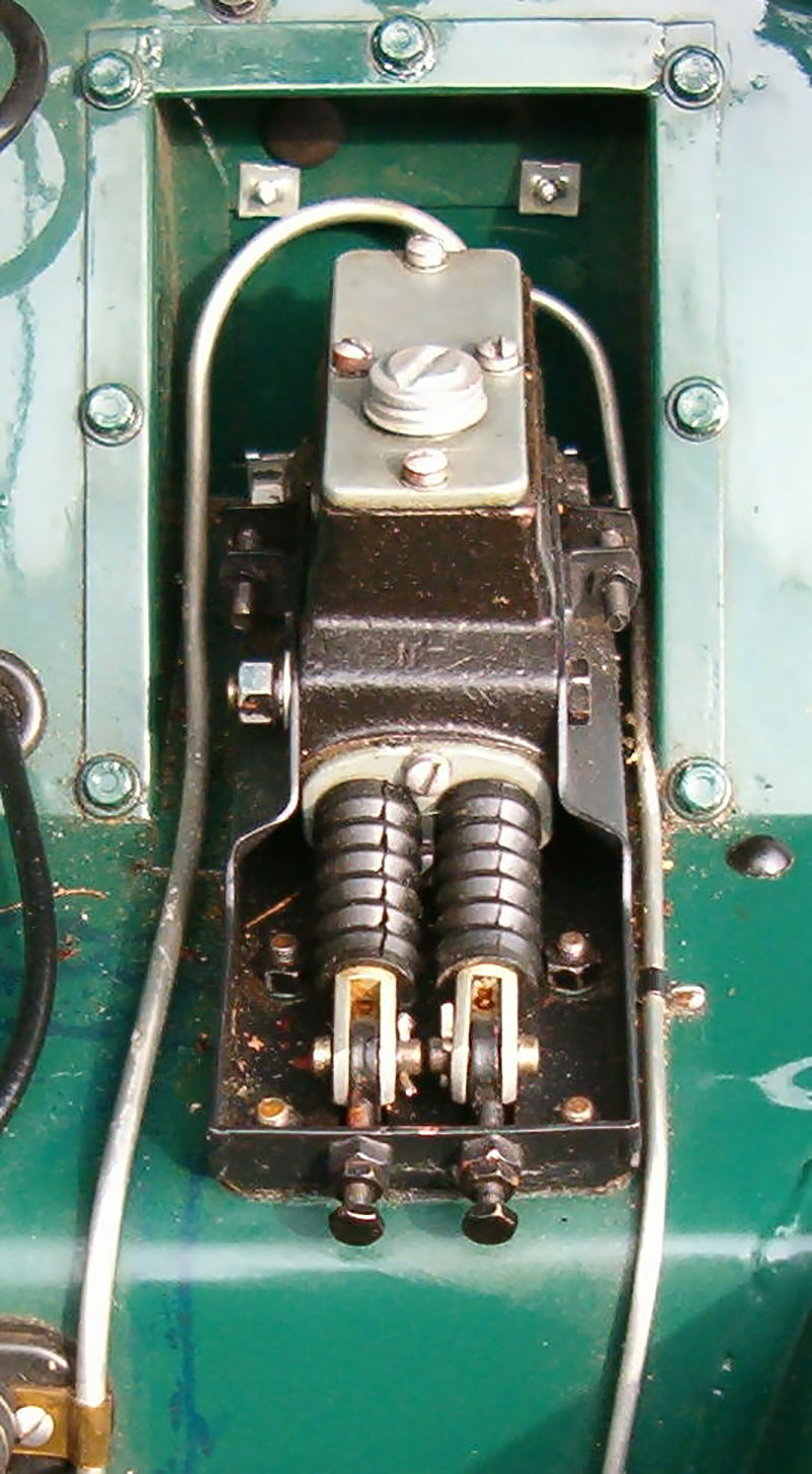
The brake pressure electrical switch was located on the left upper frame (as you face the front of the vehicle).
Interior
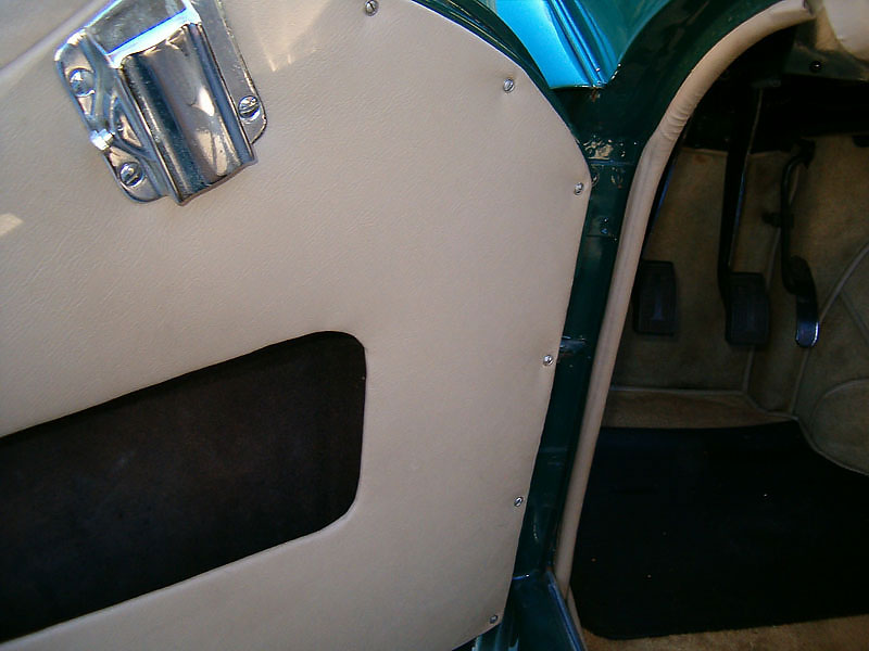
All interior panels were attached with No. 4 metal screws with matching cup washers.
The early TR2’s through commission number TS6156, did not have a center vent behind the bonnet so therefore the tonneau capping piece above the dash was solid with no center hole for a vent control. Beginning with commission number TS6157, a center vent was added.
The Tenax studs for attaching the front edge of the tonneau cover on the early TR2’s through commission number TS1871, were located directly behind the windscreen. The early Tenax studs behind the windscreen bolted directly through the cowl and were the machine screw type. This made the front edge of the tonneau cover difficult to attach. Beginning with commission number TS1872, the Tenax fastener studs for attaching the front edge of the tonneau cover were moved and screwed directly through and into the dash capping piece itself. The later Tenax fastener studs were therefore the wood screw type. The earlier tonneau cover is slightly longer from front to back to accommodate the difference in the location of the frontmost Tenax fasteners. As a result, the earlier and later tonneau covers are not interchangeable.
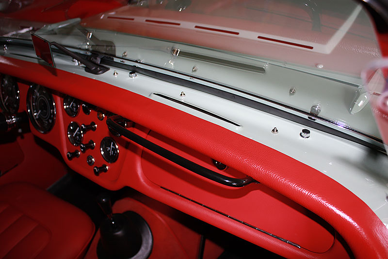
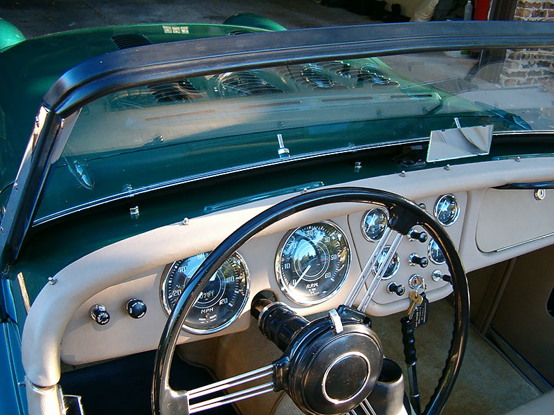
Four chrome capping bolts with chrome washers were present between the windscreen and tonneau capping piece above the dashboard. The chrome capping bolts sealed off the holes where the optional competition racing windscreens attached to a captured nut affixed to the underside of the cowl. This feature continued on TR3 models through commission number TS32833.
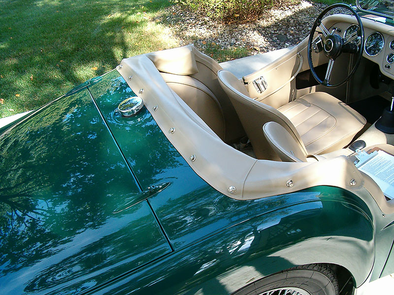
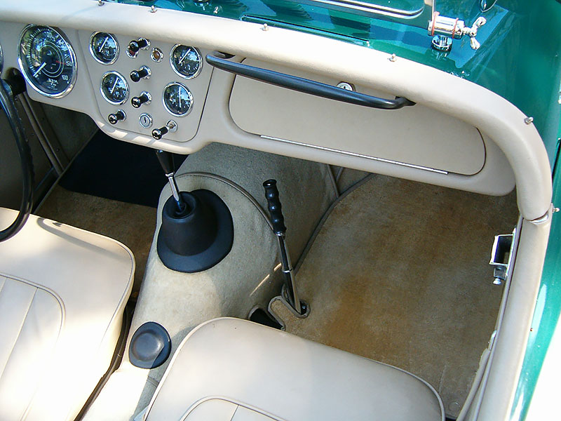
The TR2 passenger grab handle was narrower than later models and was coated with black plastic rather than chrome plated.
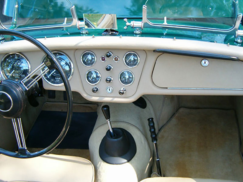
The TR2 center instrument panel was covered with the same color vinyl as the dashboard rather than painted with black wrinkle paint.
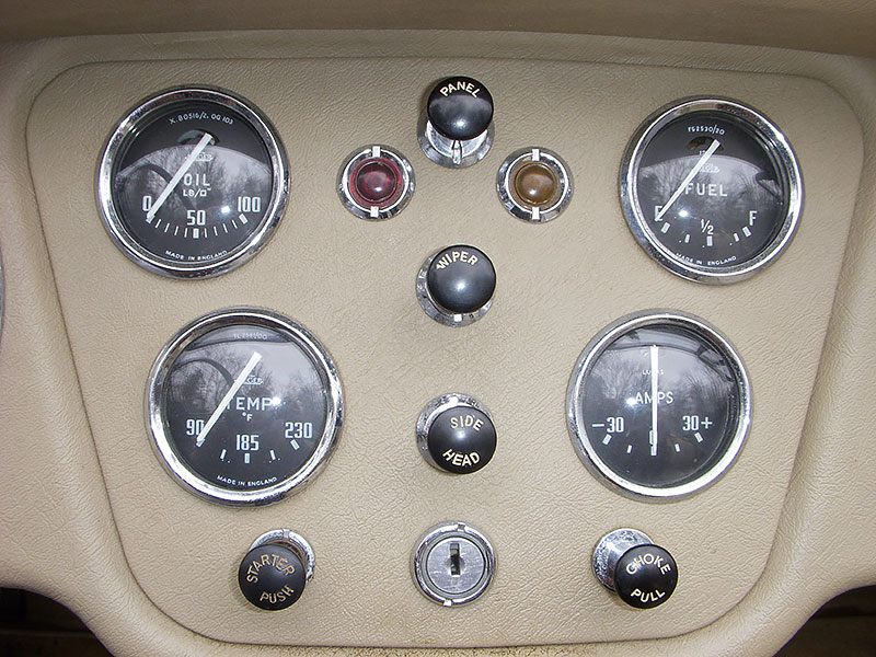
The starter button knob on the early TR2’s included only the word “STARTER” whereas the starter button knob was labeled “STARTER PUSH” on the later TR2’s. In addition, the choke cable knob on the early TR2’s included only the word “CHOKE” whereas the choke cable knob on the later TR2’s was labeled “CHOKE PULL”.
The RPM counter (rev counter) on approximately the first 1100 TR2’s did not have a red line at the 5000 RPM mark. Beginning at circa TS1100, a red line was added at the 5000 RPM mark. The various editions of the Triumph spare parts catalogues used the same Triumph part number (#106970) for both types of rev counters.
The overdrive switch (if equipped) was a push/pull type similar to the panel light switch. It carried the words “overdrive pull” (through commission number TS6265 only). Thereafter the more common “pear-shaped” overdrive switch was used.
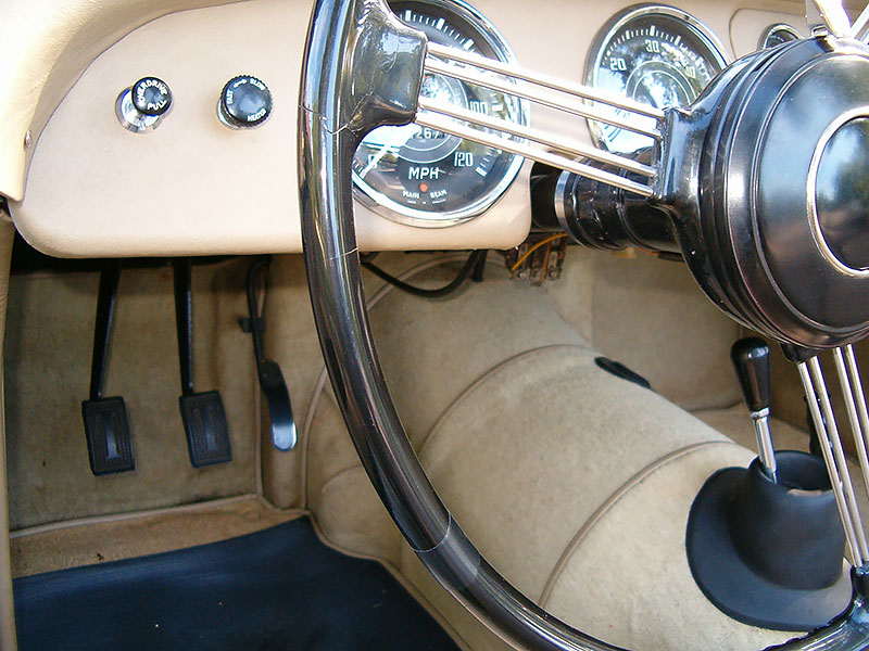
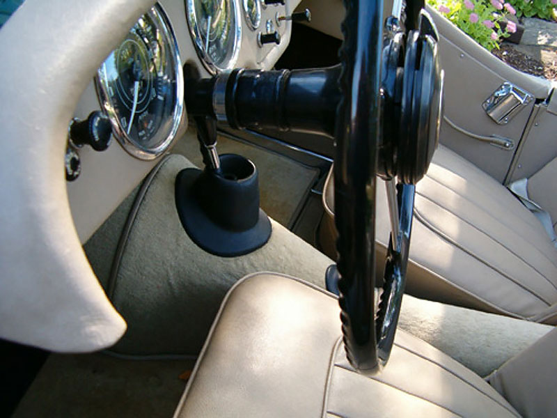
Adjustable steering was also available as an option. The adjustable steering wheel is easily recognizable by the difference in the positions of the steering wheel spokes. Notice that the spacing between the two inner wires is noticeably further apart on an adjustable steering wheel compared to a standard steering wheel.
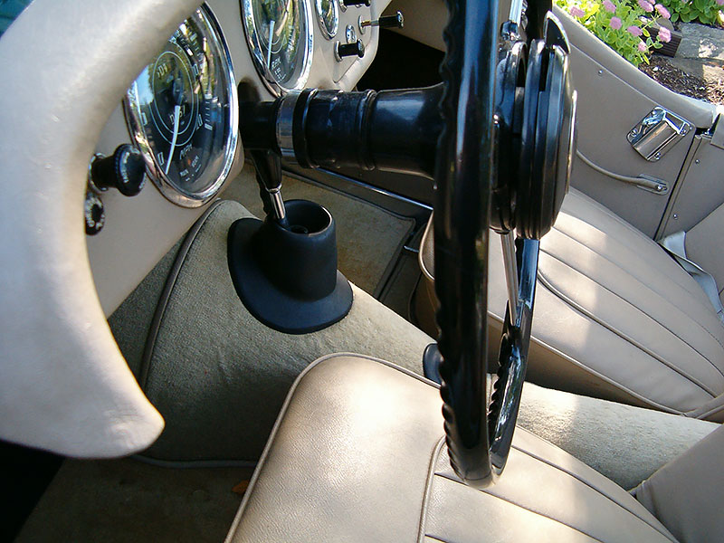
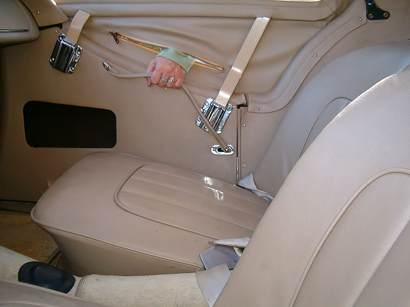
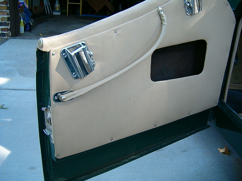
Interior door pulls were leather straps the same color as the door panels and attached to the doors at the front-most end with a plated arrowhead and screw at the top of the door panel. The rearmost end was attached with a plated acorn nut to a stud protruding through the door panel from the door latch mechanism.
Chrome plated escutcheons were used under the rearmost end of the door pull between the door panel and the door pull.
Chrome plated “wedge type” side curtain brackets were used on the TR2, TR3, and TR3A models through TS28825. The sidecurtans were secured to the wedge type brackets with a knurled nut.
Through commission number TS4228, the bonnet release was located on the right side of the interior just below the dashboard. The release looks like a choke cable with a color keyed knob (black or tan) with no lettering.
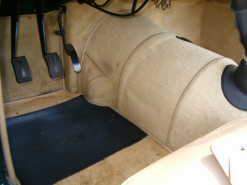
TR2 clutch and brake pedal pads did not have a “T” molded into the rubber. Instead, ribbed vertical lines were molded into the pads. Because the pedal pads are a constant area of wear, most TR2 pedal pads have been replaced with the more familiar and readily available pedal pads used on the TR3/3A/3B/4/5/6’s with a “T” molded into the rubber.
The brake and clutch pedal assembly was different on vehicles with the Lockheed twin master cylinder (through commission number TS13045) and is not interchangeable with that of later models. This difference is attributable to the distance between the push rods (master cylinder end) actuated by the pedals on the Lockheed twin master cylinder compared to the two separate cylinders used in the Girling braking and clutch system fitted to commission numbers TS13046 onward.
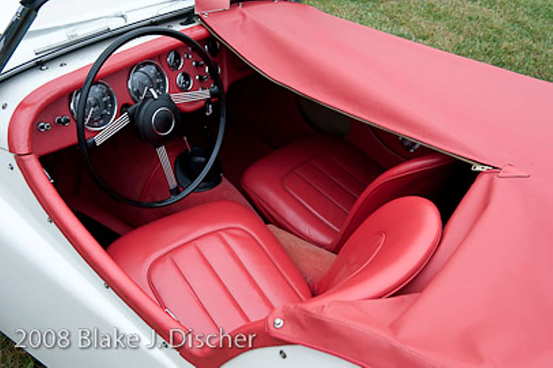
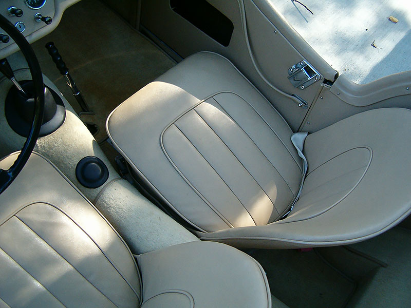
Upholstery colors initially available included blackberry, geranium, and gray. Upholstery colors brown, stone, and red were added later in the TR2 model series
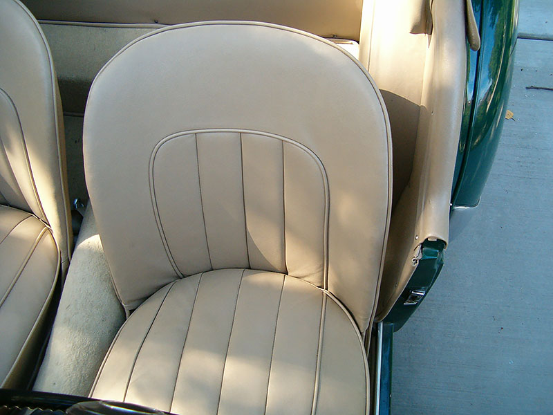
The seat squabs were squared off on the front corners and featured four longitudinal pleats as on early TR3’s. The seat backs were not padded as thickly as those on TR3A seats.
Seat upholstery piping on TR2’s was the same color as the seats rather than a contrasting color as on TR3’s.
TR2 seatbacks were rigid and neither seat back folded forward. Beginning with commission number TS8637 (the first TR3), the passenger seatback folded forward.
The carpet set consisted of 26 separate bound pieces glued down with the exception of the pieces below the feet which were attached with snaps.
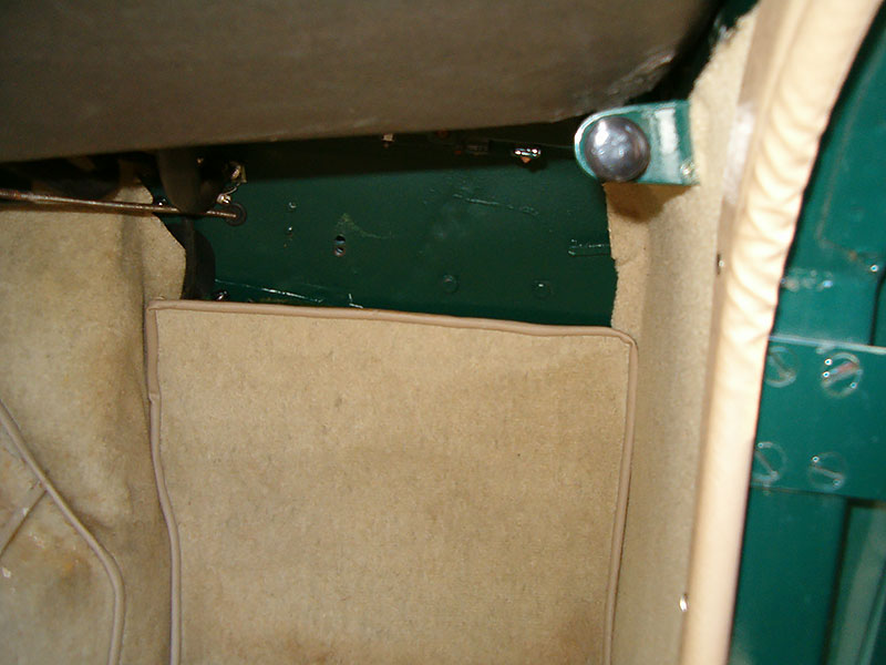
No carpet clips were present on the firewall since the vertical part of the foot well was carpeted with a separate glued-on piece.
The carpet colors available included geranium, stone, brown, blackberry , red, and gray.
The carpet was cut-pile (approximately ¼ inch thick), non-loop wool material similar to Wilton II wool carpet.
A heel pad was present on the driver’s side carpet only. The material used for the heel pad was similar to running board material with ridges going left to right.
According to the various Triumph Parts Catalogue editions, beginning with TS5089, rubber floor mats (part numbers 701238 (RH) and 701237 (LH)) were offered. These were substitutes (not overlays) for the underfoot carpet pieces in front of the passenger and driver-side seats. As of this writing, it is not clear whether they were installed by the factory or were simply available.
An overdrive transmission was available as an option. Pre- TS5980, the overdrive used a 1⅛” diameter operating piston, and the overdrive operated on fourth gear only. Post- TS5980 (or TS6226?), a 1⅜” operating piston was used and the overdrive operated on second, third, and fourth gears.
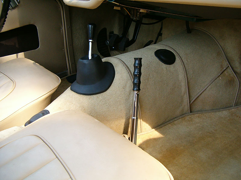
The gear shift lever on the early TR2’s through commission number TS2876 consisted of two separate pieces. Beginning with commission number TS2877 through the TR3B’s, the more familiar one piece of gear shift lever was fitted.
A transmission fluid level dipstick was present along with a rubber access plug located on the right side of the transmission cover.
Rubber access plugs for the transmission dipstick and universal joint, as well as the stick shift lever grommet, fit down on top of the carpeting. No carpet binding was present around these openings unlike later models.
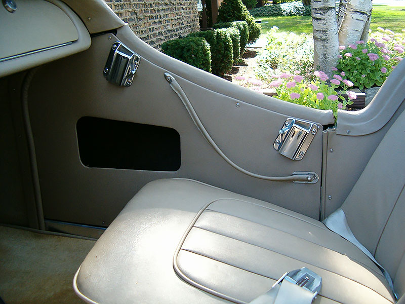
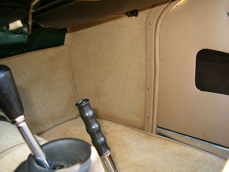
Draft excluder seals (two per door) were located along the back edge of the side footwells between the front leading edge of the door and the side footwells, and just behind the rear vertical edge of the doors under the interior dogleg panels. The draft excluders were covered with vinyl to match the door panel material, rather than fur-flex which was used on TR3 and TR3A models.
The draft excluder seals were attached to the edge of the side footwells with vinyl covered plywood doglegs matching the contour of the rear edge of the side footwells. The plywood dogleg strips were approximately ¼ inch thick and ⅞ inch wide with beveled edges and were attached to the side footwell panels wih screws.
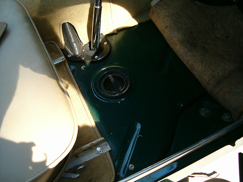
The jack aperture covers located on the floor in front of the seats on TR2’s were made of steel not rubber with a spring steel crosspiece to hold them in place. The jack aperture covers at some point may have been changed to a rubber plug but there is some confusion about the exact changeover date. We know for certain that as late as TS7093 the jack aperture covers were still metal. Contributing further to the confusion, both types of jack aperture covers were designated as Triumph part number 603384 in parts catalogue editions 1, 2, 3, & 4.
The TR2 tonneau capping pieces located just behind the doors, fit down over the top of the interior dogleg panel unlike later models where the dogleg interior panels fit over the tonneau capping piece.
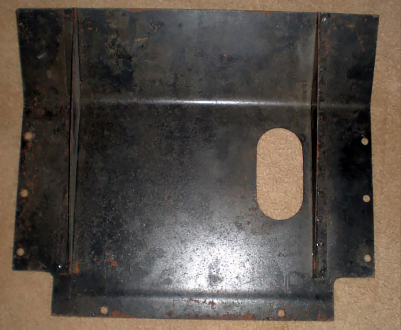
The interior petrol tank cover panel was made of Rexine-covered millboard. No pleats were present.
The interior of the boot floor only was covered with a single piece of carpet with no bound edges, and was attached with six screws and cup washers (three screws on each side). There were no coverings of any sort on the boot side areas or the wheel arches.
The petrol tank cover inside the boot was made of Rexine-covered flat millboard, generally, the same color as the interior; although, there are some seemingly original TR2’s where the boot side petrol tank cover was the same color as the exterior paint.
Frame Details
Suspension parts and frames were painted what was known as “gloss black” at the time. Today the gloss black paints that are available on the market are considerably more glossy (or shiny) so care should be taken when restoring your vehicle to make sure not to use high gloss black.
TR2 frames were generally painted gloss black as were all suspension parts. However, there are rare instances where body colored frames were fitted from the factory on a special order basis.
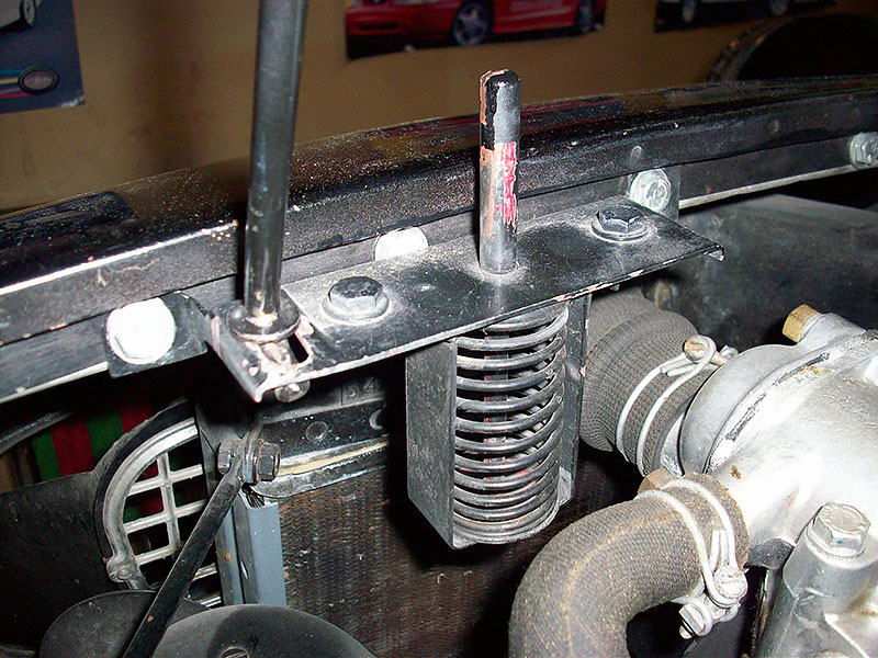
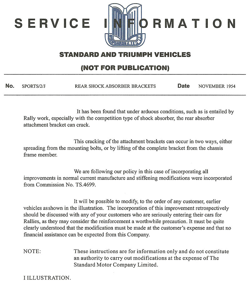
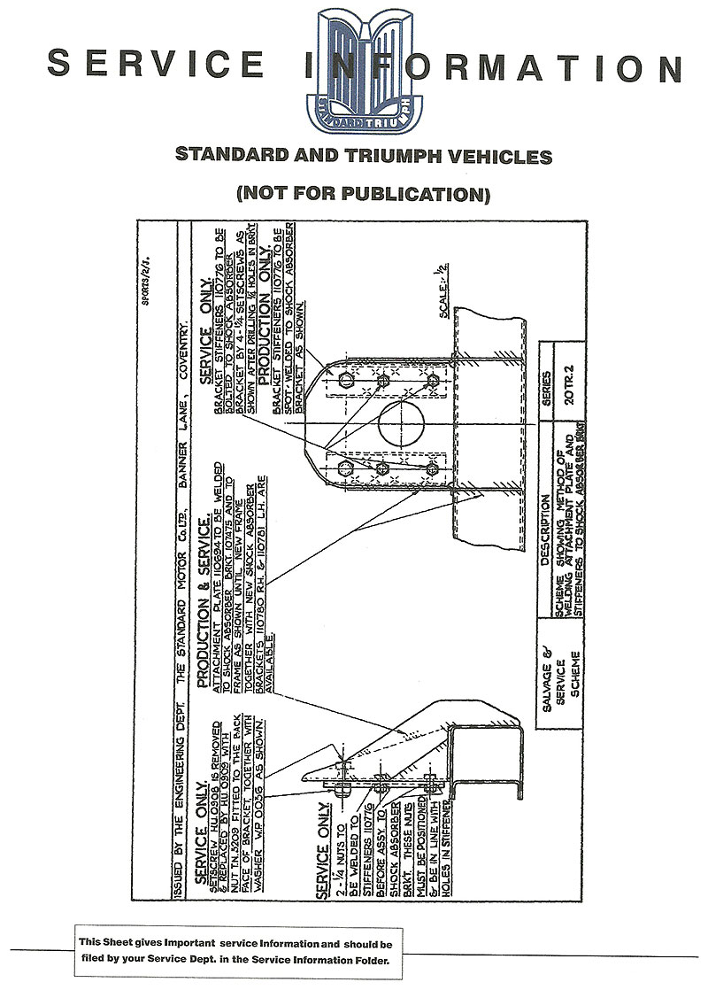
Early TR2 frames had no buttresses welded to the frame where the rear lever shock absorbers were mounted. Early on this was recognized as a weak area so several attempts were made to “beef up” this area. Finally, beginning with TS4699, substantial buttresses were added to the frame in this area for additional strength. The factory issued a factory service bulletin which included instructions for retrofitting the buttresses to earlier frames. (See Factory Service Bulletin – rear shocks pg1 and rear shocks pg2)
Beginning circa TS1300, the frames were manufactured by Sankeys. Prior to that, the frames were manufactured by the Triumph factory.
Frame types were numbered however each individual frame did not have a unique number. The frame type tags were welded onto the top front major cross member piece. As previously indicated, approximately the first 1300 frames were manufactured in the Triumph factory and carried the designation “Z10 through possibly Z19”. The frames manufactured by Sankeys carried the designation “Z21 through possibly Z29”.It appears that after the split column steering was introduced, the frame designation may have changed again to “Z31”.
The slot where the lifting jack is inserted into the frame was modified beginning with commission number TS5469, to accommodate the stronger lifting jack as mentioned in the Exterior Section of this article.(See the Factory Service Bulletin – lifting jack – frame pg1 & frame pg2)
The front wheel hubs changed several times before circa TS5000 to alleviate cracking. Some early hubs have grease nipples. Others include an attempt to strengthen them by reinforcement. After circa TS5000, the hubs were the same until disc brakes were introduced on the TR3 model.
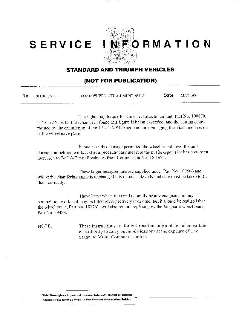
Beginning with commission number TS1634, the external size of the lug nuts used for attaching the steel wheels was increased to 7/8 inches from the previous 11/16 inches. This required that the wheel brace (lug wrench) be changed as well to 7/8 inches. It was found that under extreme competition conditions the 11/16 inch lug nuts could pull through the steel wheels. (See the Factory Service Bulletin – wheel nuts).
Beginning with approximately commission number TS1869, the road wheels were changed in such a way that the center portion of the wheel was now welded onto the outer portion of the steel wheel. This is a difficult change to explain in words but is quite noticeable if one views a pre-TS1869 versus a post-TS1869 steel wheel.
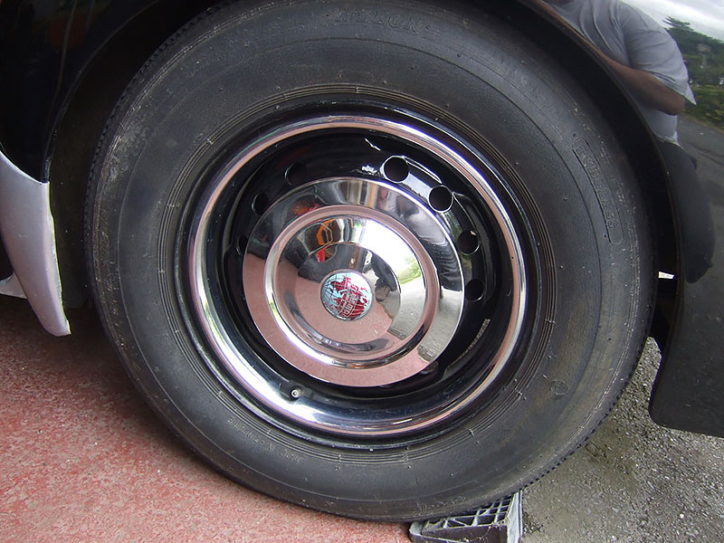
The steel wheels on all TR2’s & TR3’s were painted body color. It was not until the introduction of the TR3A model in 1958 that steel wheels were painted a silver/aluminum color. The optional 48 spoke wire wheels were painted silver/aluminum.
The front brakes were 10″ x 2¼” drum type on all TR2 production cars. Only the prototypes were fitted with 9″ x 1¾” drums. Front wheels were equipped with Lockheed twin wheel cylinders on each wheel.
The rear brakes were 9″ x 1¾” drum type through commission number TS5442. Beginning with commission number TS5443, the rear drums were increased in size to 10″ x 2¼”. Both sizes used a single Lockheed wheel cylinder.
The differential utilized course splined axle shafts (vs. the TR3’s fine splined axle shafts) and had characteristic four-bolt outer axle bearing housings. The brake backing plates bolted on with four bolts.
The early prototype cars had a rear axle ratio of 3.89:1 (using 5/16” crown wheel bolts). Production TR2 model cars had a rear axle ratio of 3.70:1 (using 3/8″ crown wheel bolts). A rear axle ratio of 4.1: 1 was available presumably after TS6226 when overdrive on 2nd, 3rd, and 4th gears was introduced.
A steel brake line behind the front-most frame crossmember connected the two front brakes.
The wire wheel splines were NOT bolt on adapters through commission number TS8637. They were separate one-piece hubs on both the front and rear. The wire wheel splines were part of the wheel hub and were attached in the front to the stub axle. In the rear, the wire wheel splines were attached to the differential axle shafts with a single center castellated nut and cotter pin.
The TS numbers stamped into the transmission and differential casings should be close to the vehicle commission number but will be slightly higher.
The pre-TS2532 TR2’s exhaust system included no resonator which resulted in a “throatier” exhaust note. Beginning with TS2532, a resonator was added which substantially reduced the noise level of the exhaust. Many TR2’s were retrofitted with the later resonator in order to quiet the exhaust.
Options and Accessories
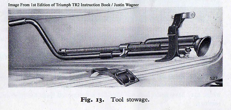
All TR2’s came equipped from the factory with a lifting jack, engine crank, and either a wheel brace (lug wrench), or wire wheel knock-off hammer if wire wheels were supplied.
Certain optional equipment items were best purchased with the vehicle upon placement of the original vehicle order with the Triumph dealer. These optional equipment items included a heater and defroster, overdrive transmission, wire wheels, steel hardtop, adjustable steering, and competition springs. These items could be ordered later through the Triumph dealership network; however, dealer installation was costly.
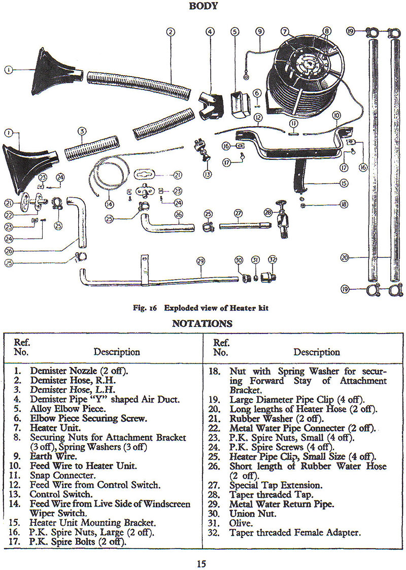
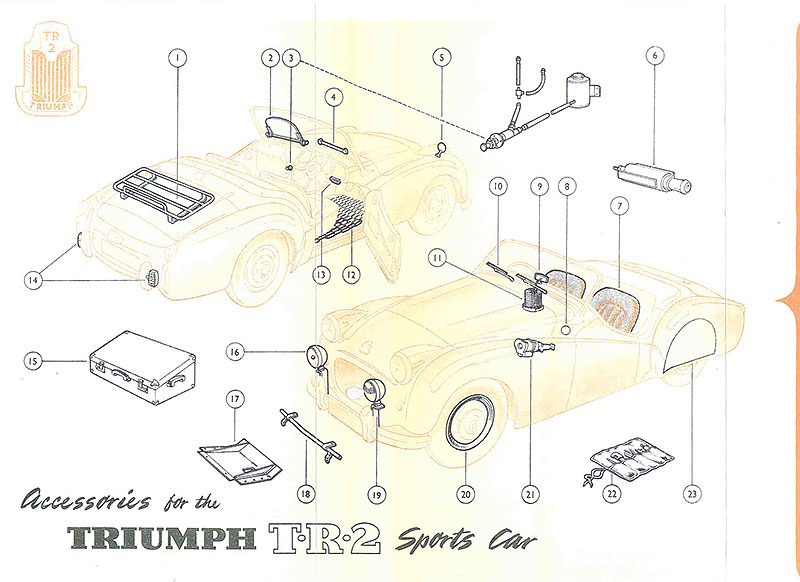
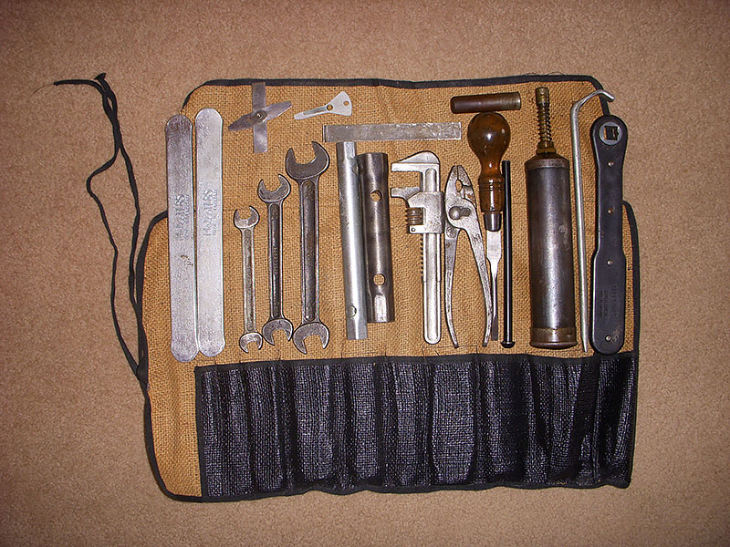
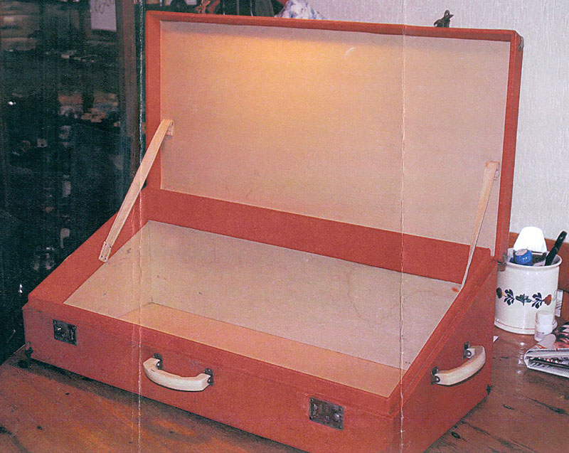
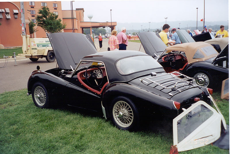
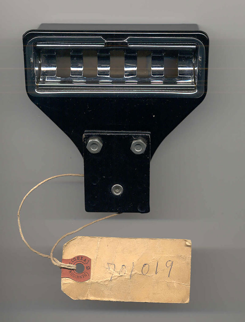
Other optional accessories which were available for purchase through the Triumph dealership network included a complete tool roll, badge bar, seat covers, tonneau cover, hood sticks cover (convertible top frame cover),wheel trim rings, rear wheel spats, fitted suitcase, luggage rack, competition radiator & sump skid shield, aluminum oil sump, undershield kit, ashtray, cigarette lighter, two speed windscreen wipers, windscreen washers, reverse light, spot lamp, (right side in picture) fog lamp (left side in picture), tailored loop floor mats, interior anti-dazzle mirror, wing mirrors, racing windscreens, and competition license holder.
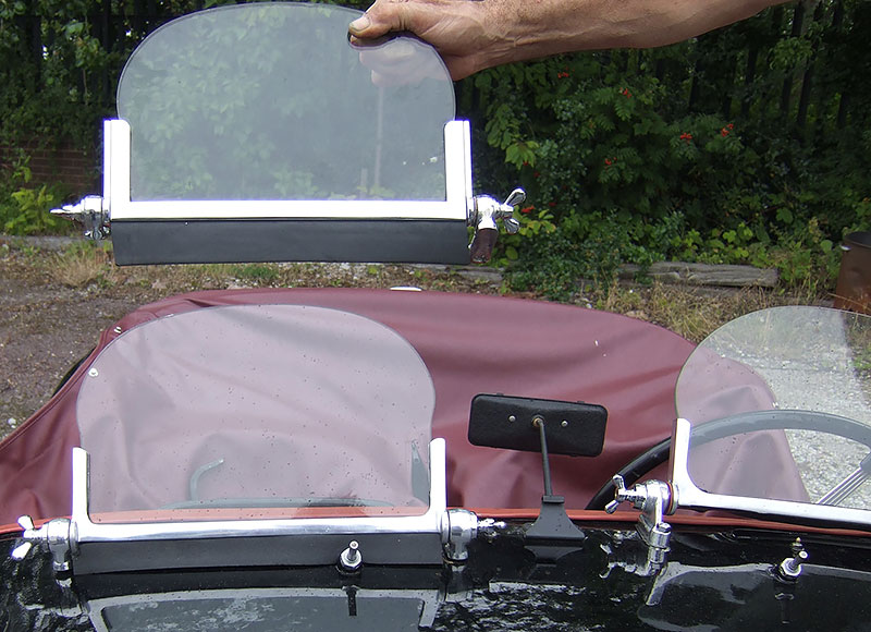
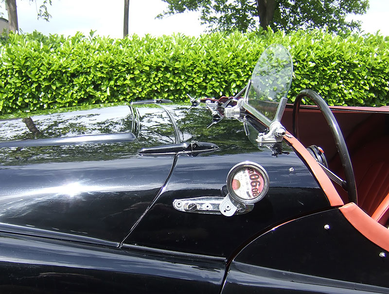
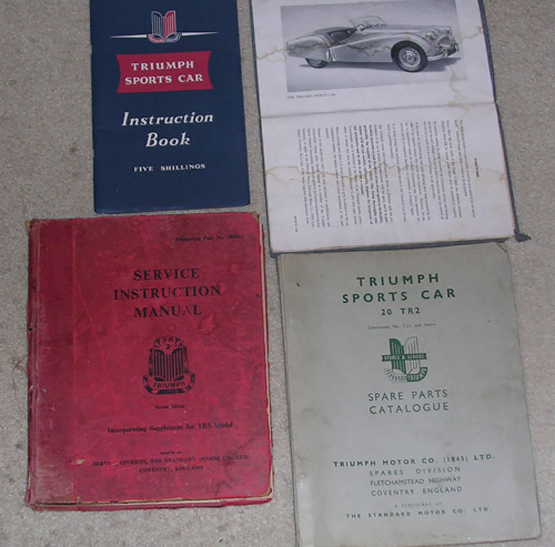
A Triumph Sports Car Instruction Book (owner’s manual) was provided from the factory in the glove compartment of each vehicle. In addition, enthusiasts could purchase from the dealer a Service Instruction Manual and Spare Parts Catalogue